What Is Flex Bend Radius?
Bend Radius (r), or Bending Radius, is the minimum degree one can bend a flexible printed circuit (FPC) without damaging it or shortening its life. The smaller the bending radius, the greater is the FPC flexibility (as the radius of curvature decreases, the curvature increases).

Bend Radius
Bend Radius according to IPC-2223
| Bending Radius | Stable | Dynamic |
| Single-Sided | 10:1 | 100:1 |
| Double-Sided | 10:1 | 150:1 |
| Multilayer | 20:1 | not recommended |
*Distinguish between dynamic (regular-to-bend) and stable flexion (bend-to-install).
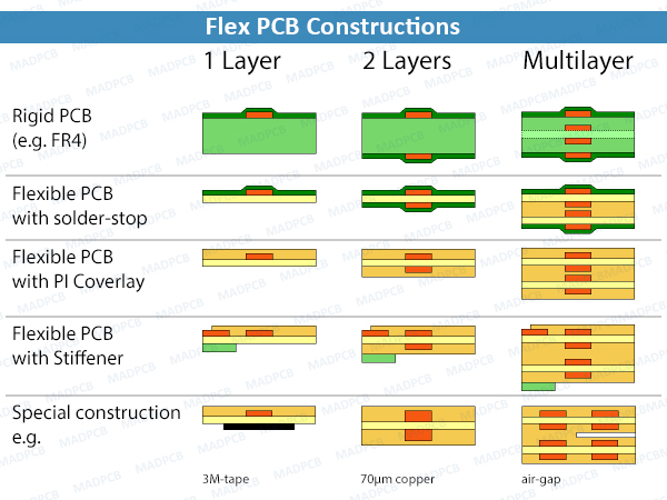
Flex PCB Constructions
Examples of the minimum bending radius of flexible printed circuit boards with assumed thickness.
| 1 Layer e.g. 90μm thickness | Stable | Semi-Dynamic | Dynamic |
| Min Ratio (r/h) | 10:1 | 20:1 | 100:1 |
| Min Bending Radius | 0.9mm | 1.8mm | 9mm |
| 2 Layer e.g. 190μm thickness | Stable | Semi-Dynamic | Dynamic |
| Min Ratio (r/h) | 10:1 | 20:1 | 150:1 |
| Min Bending Radius | 1.9mm | 3.8mm | 29mm |
| 4 Layer e.g. 290μm thickness | Stable | Semi-Dynamic | Dynamic |
| Min Ratio (r/h) | 20:1 | 50:1 | not recommended |
| Min Bending Radius | 5.8mm | 15mm | not recommended |
If possible, limit the number of flex layers to 1 or 2, for maximum mechanical flexibility and cost savings. Pay attention to a symmetrical stack-up of the printed circuit board. The flex layers continue within the rigid part as inner layers and can there be used for conductor routing. The minimum bending radius is usually between 1mm and 6mm. The dynamic bending stress can only be reliably ensured with single- and double-layer flexible PCBs.