Table of Contents
Copper in Printed Circuit Boards
Printed circuit boards (PCBs), or called printed wiring boards (PWBs), have become basic parts in almost all areas of modern technologies. Copper trace is a crucial element on circuit boards. The copper always plays a role of carrying electrical signals to different components across the board assembly. Without traces, the PCB will not function. Of all the elements that build PCB boards, copper is one of the most important.
Why Choose Copper to Fabricate PCB?
The metal used in PCBs are small amount and thin. One ounce (1oz) copper can be turned into 35 micrometers (μm) about 1.4mil thick, which can cover 1ft2, or 0.093m2 of PCB substrate. There are many reasons as following why people in PCB industry choose copper to fabricate printed circuit boards.
- High conductivity
- Good flexibility
- High temperature resistance
- Good chemical resistance
- Easy to get
- Abundant supply with fairly inexpensive cost
- Faster etching speed than many metals
Why Need Surface Finish on Copper Features?
Copper used in PCB manufacturing has many pros, but copper does also have a specific con, which is that copper corrodes at a faster rate than many other metals. This carrion results in oxidation, called “Back Pads”, which impedes bonding, soldering, fusing, and it creates high resistance in surface contact. Thus, most flexible circuits and rigid boards require a surface finish to cover the copper features. The surface finish on copper features has 4 main considerations as below:
- Prepare Soldering: Soldering assembly is probably the most common operation for flexible circuits assembly. Soldering is actually a fairly complex process as different metals flow together and combine to form a new alloy that creates an intermetallic layer. This intermetallic connection creates an excellent electrical and mechanical bond. Soldering requires a very clean surface and just about any degree of oxidation can impede the process, so the surface treatment needs to keep the copper oxide-free until soldering is completed.
- Resistance to Surface Abrasion: Applications involving surface contact create a different challenge. Dome switches and pressure type connectors make multiple contact with the flexible circuit and rely on a corrosion-free surface for adequate electrical contact. Since the mechanical abrasion can mar a soft surface, hardness to resist abrasion is a key feature.
- Wire Bond Assembly: Wire bonding places a different kind of requirement on the surface. Ideally, the surface must be oxide-free and soft enough to form around the wire or ball that gets pressed against the surface with heat. The metal surface must be compatible with metals used in wire bonding and be able to indefinitely hold a good electrical and mechanical connection. Both gold ball bonding and aluminum wedge bonding are widely used for direct chip attach components.
- Bendability and Flexibility: Another consideration when choosing a surface finish for a Flex PCB is the bendability and flexibility. Metals such as tin, gold and solder may not be able to withstand bending or flexing, so, more pliable surface treatments may be required or a surface treatment needs selective application. Feature density is another factor that eliminate some surface finishes as a viable option. For fine pitch components or small vias, the topography and thickness of the finish plays a critical part in successful component assembly.
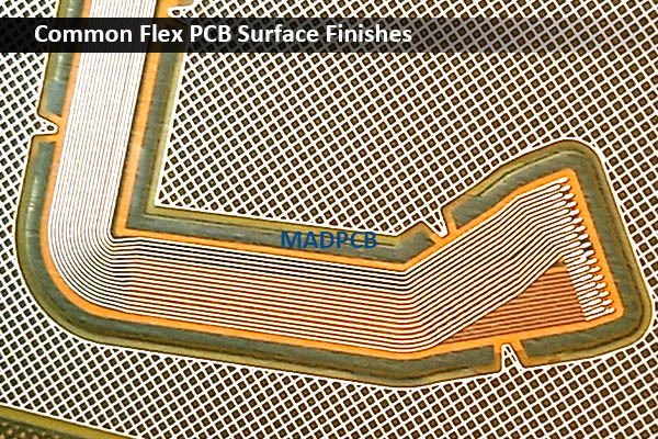
Typical Surface Finishes in Flex PCB
Most Flex PCB manufacturers offer a variety of surface finishes, as application requirements differ widely. Following are some typical single surface finishes in flex PCB.
Organic Solderability Preservative (OSP)
OSP is the most environmentally friendly (RoHS compliant) surface treatment and is fairly inexpensive. OSP is applied by spraying or dipping, and typically is formulated to only bond to copper. OSP has a limited shelf life, while it does a reasonable job of inhibiting corrosion, an aggressive flux is usually required for excellent soldering. OSP should be considered a short term for preventing from oxidization.
Electroless Nickel / Immersion Gold (ENIG)
ENIG, or just called immersion gold, is considered by many to be the ideal RoHS compliant surface, a RoHS compliant finish for solder paste reflow. Not only does the surface easily accept solder, but it is very smooth and flat, allowing easier placement of small components. ENIG is also an acceptable surface finish for direct chip attach with aluminum wire bonding. The electroless nickel is used as a barrier metal between the gold and the copper to prevent copper from migrating into the gold and avoid corrosion by galvanic action. Immersion gold is thin enough (typical Au: 2-3μ’’, Ni: 120-240μ’’), so it does not create a problem with gold embrittlement.
Immersion Silver
Immersion silver treatment is most frequently used when solder paste contains silver for enhanced compatibility with subsequent soldering processes. Silver dissolves into the solder during the reflow process. While storage conditions affect shelf life, immersion silver is considered a RoHS compliant surface with a limited shelf life. It should be soldered fairly soon after fabrication. Silver should not be left on the copper indefinitely as it is susceptible to dendritic growth.
Silver also has a propensity to oxidize, but this is generally more of a cosmetic issue than a surface contact issue since silver oxide is actually very conductive.
Immersion Tin
Immersion tin, also a RoHS compliant surface, will behave similarly to immersion silver. It is coated to about 25-60μ’’ thick and will do well for short term oxidation prevention. Over time tin will oxidize and can also experience dendritic growth issues. Immersion tin over copper forms an intermetallic (IMC) layer. Over time, the copper-tin intermetallic layer continues to grow. Flex PCB soldering must be done to the tin and cannot be done directly to the intermetallic alloy. If too much time passes, there won’t be tin left for adequate soldering.
BTW, the chemicals of immersion tin may shock the small circle features of the silk screened or printed legends in flexible printed circuit (FPC) manufacturing. Otherwise, customers accept such kind legend defects, MADPCB will not recommend immersion tin surface finish in flex PCB.
Hard Gold
Applications requiring a highly conductive surface contact create a different challenge. Hard gold is often the selected flex PCB surface finish with tactile metal domes, formed rubber domes, and pressure type connectors. These copper features rely on a corrosion-free surface for low resistance electrical contact. In these cases, the surface finish needs to wear resistant with multiple insertions and/or contacts a common requirement.
An electrolytic hard gold surface is solderable but the additives that harden gold may make the process more difficult. Flexibility of this plated surface can also be an issue. While the gold itself is very flexible, the nickel barrier metal is somewhat brittle. Hard gold over nickel is often acceptable for limited flexing, such as flex to install, but not recommended for areas that are exposed to frequent or shape bending.
Soft Gold
Soft gold is typically used for gold ball wire bonding for direct chip attach component assembly processing. Soft gold does provide a solderable surface, but would be an expensive choice if no wire bonding is needed. Electroless nickel immersion gold (ENIG) would be a more suitable choice when standard surface mount soldering is required.
Like most of the metal surface finishes, soft gold/nickel are also RoHS compliant surface finishes, and must be kept away from areas that need to bend or flex.
How to Find the Right Flex PCB Manufacturer?
When selecting a flex PCB manufacturer in China, consider these essential factors:
- Response Speed: If the sales or engineers in a flex PCB house can provide fast response to your RFQ or questions, this indicates this company has good knowledge of flex PCB manufacturing, stack-up and pricing. Like rigid board, the price calculations of flexible PCB are also based on square meters. But before quote, it requires to panelize the boards, and make a stack-up, no matter you prefer Unit (single pieces) delivery or Set delivery. The width of most commonly used FCCL is 250mm. If your flex PCB is large, we may need to use FCCL with 500mm in width.
- Flex PCB Manufacturing Experience: Successful flex PCB fabrication requires high-end equipment and rich experience to guarantee high quality output. In the fabrication process, flex PCB materials’ movement between layers and materials’ thermal expansion and cool shrink are vital to lamination result and registration. If your circuit need PCB assembly. Just find and select a reliable turnkey manufacturer, which has extensive experience in flex and rigid-flex circuits, to ensure it has the require capabilities and knowledges to meet your project requirements and standards.
- Impedance Control (if required): Modeling and manufacturing impedance-controlled flex and rigid-flex PCB is more demanding. Different materials (FCCL, adhesive, coverlay, CCL and PP) from different manufacturers are different. The dielectric constant (DK) values supplied can be inaccurate, and online free modeling software usually returns erroneous values, and can only model simple trace to plane structures. Working with flex PCB manufacturer, like MADPCB, the stack-up, modeling and impedance calculations can be provided you in the offer. After fabrication, we will measure the test coupon and get the actual impedance-controlled value(s). Then test coupon and testing report will be shipped together with your bare boards or board assemblies.