Table of Contents
Thermal Simulation and Analysis Services
Most electronic components dissipate heat whenever current flows through them. The amount of heat depends on the power, device characteristics, and circuit design. Besides the components, the resistance of the electrical connections, copper traces, and vias contribute to some heat, and power losses. To avoid failures or circuit malfunctions, PCB designers should aim at producing PCBs that operated and remain within safe temperature limits. While some circuits will work without additional cooling, there are situations where adding heat sinks, cooling fans, or a combination of several mechanisms is inevitable. Here we will discuss design practices that conducting thermal analysis.
Why Need Thermal Simulation?
Thermal simulation is an important part of the PCB design process, especially if modern, ultra-fast components are used. For example, FPGAs or fast AC/DC converters may easily dissipate several watts of power. Because of this, PC boards, enclosures and systems must be designed to miniature the impact heat will have on their proper functioning. Sometimes it becomes a considerable constraint on the developer’s creativity. For example, an air-cooled design on a 3U Compact PCI Express card may be limited to only 20W before some serious thermal problems start to develop on the board due to insufficient airflow between boards and between parts on the board. Complex designs aren’t the only boards any systems that need to be checked for thermal violations. A simple handheld gadget -a mobile- may also overheat under certain conditions. Many people are familiar with the user, and they also can contribute to accelerated aging of the battery, possibly even causing a fire.
If you are developing a PCB board that will be only made in small quantity and used in your own lab for a single purple it still makes sense to verify the board will work. As an example, we saw a microwave board that was carefully laid out and validated in an EMS simulator. It actually performed very well, RF-wise. However, the designer, focusing exclusively on microwave components, neglected to calculate the power that is dissipated by the many regulators that the board had. Those regulators were not given enough copper to dump the heat into. As result, while the board was great in RF terms, within minutes it heated up almost to the ignition point -it couldn’t be touched, and it couldn’t be allowed to run because the regulators would burn out and the unregulated power would likely damage everything else. That board, without rework, could not be used even in a lab environment; it was nothing short of a fire hazard. A couple of formulas and a quick simulation could have prevented such a problem.
We can use specialized CAD software that allows a designer to enter a 3D model of the entire device -that includes the board with components, fans (if present), and the enclosure with ventilation openings. Then heat sources are added into simulated components – typically into models of ICs that produce enough heat to be concerned. Ambient conditions are specified, such as air temperature, vector of gravity (for convection calculations) and sometimes external radiation load (such as solar.) Then the model is simulated; results usually include temperature and airflow plots. Within enclosures it is also important to get pressure plots.
Below is a custom Ethernet-controlled human interface device; it has a few voltage regulators, it has a processor, and it has a separate Ethernet bridge. Below is the rendered image of the PCB assembly, as it is produced by the mechanical design toolchain.

Thermal Simulation 3D PCB Assembly
We import this model into thermal simulation CAD. This complex 3D computation fluid dynamics software that predicts airflow and heat transfer in and around electronic equipment, including the coupled effects of conduction, convection and radiation.
First, we take out mechanical 3D model of the PCB board assembly and import it into the software. As the CAD imports our model it reorganizes it for simulation purposes. For example, cylinders of capacitors will become cubes. This makes the analysis simpler and faster. Smaller features are automatically removed, unless we want to keep some.
In the next step we insert power sources into parts that we are interested in. Most components in this design produce little or no heat, and we do not need to simulate their contribution to released energy. For this example, we specify four heat sources that vary from 0.1 to 1Watt and place them within appropriate components where the heat-producing dies are located.
Next, we specify materials for the PCB board itself (a FR4 laminate) and for some components (epoxy resin, acrylate plastic, aluminum alloy etc.) -all standard materials in this tool’s library. We could also create a new material and enter its unique thermal characteristics.
We complete the configuration by entering various initial conditions -the ambient temperature and pressure, the nature of the coolant (air of 30°C in this case,) orientation of the board in Earth’s gravity field (this tells the software which way the hot air will rise) and a few more. Then we run the simulation.
To perform the simulation, the software slices the entire model into a large number of elements, each with its own material and thermal characteristics and boundaries to other elements. Then it simulates conditions within each element and slowly propagates them to other elements according to materials’ specifications. Thermal simulation and analysis will help better PCB design.
How Hot Does Your Design Become?
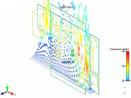
The first plot to look at is surface temperature plot. It is seen in a projected view and annotated to exactly measure temperatures in key points.

Thermal Simulation
Colors in this plot indicate temperatures; blue for colder areas and red for hotter areas. The legend on the side explains colors in between.
The PCB board is simulated in +25°C air. We can easily see “hot spots” on the board that correspond to major heat sources -two voltage regulators (IC1, IC3), one processor (IC2) and one Ethernet bridge. This plot helps us to verify the surface of provided copper that acts as a heatsink for bother regulators.
We can see that the temperature of critical components is within the allowed range; however we not that the ambient temperature of the model is only +/-25°C. If the device is being designed for operation at higher temperatures then improvements may be needed to bring the design into compliance. Such improvements may include optimization of power distribution mounting heatsinks onto some parts, increasing the copper surface under surface-mounted regulators, using forced airflow (by adding a fan), using heat pipes, spray or conductive cooling, and many more options.
Where the Air Is Coming from and Going to?
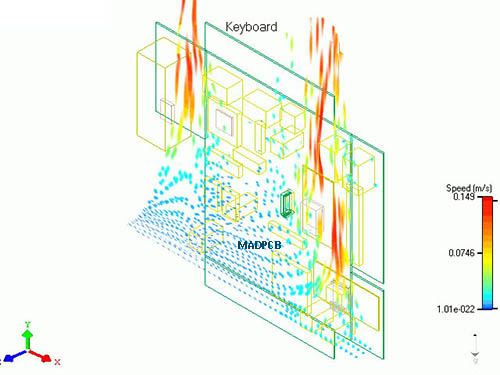
Understanding how hot the parts of the PCB board will become is the first step, but we also want to see how the air is moving around the board. This is important because we will want to make ventilation holes in the enclosure. In some designs, hot air from one part rises to heat some other part; if that causes a problem, then parts need to be rearranged, or air ducts may be required to control the flow of air. Below are two plots of the airflow around out example board.

Thermal Simulation
Here you can see the airflow plot over the components surface of the board, as seen through the board, Blue color corresponds to low air speed (zero) and red color corresponds to higher air speed -in this case top speed is 0.15m/s. These are typical values for a convection cooled design without fans. We can see how the heat originates at heat sources and propagates upward, merging with other hot streams and flowing around other components on the board. We can clearly see where we should place a ventilation grille in the housing.

Thermal Simulation
This plot tells us that the solder side (back) of the board is producing less than half the heat compared to the component side (front), and can be translated into temperatures of front and back panels of the enclosure, if the board is to be placed into it.
Particle Thermal Simulation
There is another popular visible thermal simulation technique called “particle simulation”. As the name suggests, the software injects a number of small particles into the flow of the coolant and then calculates how those particles move within the simulated system. This is a very powerful method because not only the designer can see how particles move, but by coloring particles one can see a secondary parameter, such speed or temperature. Below is the particle simulation of our sample board. Particles are inserted at the bottom of the board and carried upward by the airflow. We generated two animations; the first uses color to indicate air speed and the second used color to indicate temperature of the air.
Thermal Simulation