Table of Contents
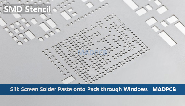
SMT Tool: SMD Stencil
Precision electrical PCB assembly attributes to a good SMD Solder Paste Stencil, which deposits appropriate solder paste (tin cream) onto the bare printed circuit boards to establish the electrical connections. To meet more and more PCB assembly demand with high-density and smaller parts, MADPCB started to provide Laser Stencils for your PCB assemblies’ quality guarantee.
SMD Stencil
As a PCB and assembly Manufacturer, all stencils from MADPCB are 100% laser-cut and made of 304 stainless steel with extremely smooth windows that provide the best solder paste release. The frameless and framed SMT stencils in various sizes are provided to accommodate all solder paste printer and stencil requirements.
Experienced PCB assemblers know that the stencil foil thickness and aperture size joint control the volume of solder paste printed on the circuit boards. A lack of paste causes insufficient solder joint. Too much paste causes solder balling, bridging, and tomb-stoning.
SMD Stencil Capabilities
| Material | Foil: 304 stainless steel
Frame: Aluminum |
| Stencil Size | 370x470mm [14.5’’x18.5’’]
420x520mm [16.5’’x20.5’’] 550x650mm [22.0’’x25.5’’] 735x735mm [29.0’’x29.0’’] *other size can be customized. *long 1600mm SMT Stencil can be provided. |
| Stencil Type | SMT Stencil [Framed SMT Stencil]
SMT Stencil Foil [Frameless SMT Stencil] |
| SS Foil Thickness | 0.10mm (4mil)
0.12mm (5mil) 0.13mm (6mil) 0.15mm (7mil) 0.18mm (8mil) 0.20mm (10mil) |
Stainless Steel Foil Thickness
It’s chosen upon the part types being placed and soldered on the circuit board. Rules should follow as below,
| ·Aspect Ratio = Stencil Thickness / Aperture Width = T/W >=1.5
·Area Ratio = Aperture Area / Aperture Walls Area = (L x W) / [2 x (L + W) x T]>=0.6 ·Circular Openings = Diameter / (4 x foil thickness) >=0.66 |
General Aperture Design Guidelines for Surface-Mount Devices
| Part Type | Pitch | Pad Footprint Width | Pad Footprint Length | Aperture Width | Aperture Length | Stencil Thickness Range | Aspect Ratio Range | Area Ratio Range |
| PLCC | 1.25mm [49.2mil] | 0.65mm [25.6mil] | 2.00mm [78.7mil] | 0.60mm [23.6mil] | 1.95mm
[76.8mil] |
0.15–0.25mm
[5.91–9.84mil] |
2.3 – 3.8 | 0.88 – 1.48 |
| QFP | 0.65mm [25.6mil] | 0.35mm [13.8mil] | 1.50mm [59.1mil] | 0.30mm [11.8mil] | 1.45mm [57.1mil] | 0.15–0.175mm [5.91–6.89mil] | 1.7 – 2.0 | 0.71- 0.83 |
| QFP | 0.50mm [19.7mil] | 0.30mm [11.8mil] | 1.25mm [49.2mil] | 0.25mm [9.84mil] | [1.20mm] 47.2mil | 0.125–0.15mm [4.92–5.91mil] | 1.7 – 2.0 | 0.69 – 0.83 |
| QFP | 0.40mm [15.7mil] | 0.25mm [9.84mil] | 1.25mm [49.2mil] | 0.20mm [7.87mil] | [1.20mm] 47.2mil | 0.10–0.125mm [3.94–4.92mil] | 1.6 – 2.0 | 0.68 – 0.86 |
| QFP | 0.30mm [11.8mil] | 0.20mm [7.87mil] | 1.00mm [39.4mil] | 0.15mm [5.91mil] | 0.95mm [37.4mil] | 0.075–0.125mm [2.95–3.94mil] | 1.5 – 2.0 | 0.65 – 0.86 |
| 0402 | N/A | 0.50mm [19.7mil] | 0.65mm [25.6mil] | 0.45mm [17.7mil] | 0.60mm [23.6mil] | 0.125–0.15mm [4.92–5.91mil] | N/A | 0.84 – 1.00 |
| 0201 | N/A | 0.25mm [9.84mil] | 0.40mm [15.7mil] | 0.23mm [9.06mil] | 0.35mm [13.8mil] | 0.075–0.125mm [2.95–3.94mil] | N/A | 0.66 – 0.89 |
| BGA | 1.25mm [49.2mil] | CIR 0.80mm [31.5 mil] | CIR 0.80mm [31.5mil] | CIR 0.75mm [29.5mil] | CIR 0.75mm [29.5mil] | 0.15–0.20mm [5.91 – 7.87mil] | N/A | 0.93 – 1.25 |
| Fine- pitch BGA | 1.00mm [39.4mil] | CIR 0.38mm [15.0mil] | CIR 0.38mm [15.0mil] | SQ 0.35mm [13.8mil] | SQ 0.35mm [13.8mil] | 0.115–0.135mm [4.53 -5.31mil] | N/A | 0.67 – 0.78 |
| Fine- pitch BGA | 0.50mm [19.7mil] | CIR 0.30mm [11.8mil] | CIR 0.30mm [11.8mil] | SQ 0.28mm [11.0mil] | SQ 0.28mm [11.0mil] | 0.075–0.125mm
[2.95 – 3.94mil] |
N/A | 0.69 – 0.92 |
(as per IPC-7525)
Note: Mix Assembly Technology with SMT Assembly and through-hole assembly (Intrusive Reflow). It is desirable to have a process where SMT and THT devices can both be provided with printed solder paste, placed on or in the PCB board and reflowed together.
Process Window for Intrusive Soldering – Maximum Limits and Desirable:
| Feature | Max Limits | Desirable |
| Hole Diameter | 0.65-1.60mm [25.6-63.0mil] |
0.75-1.25mm [29.5-49.2mil] |
| Lead Diameter |
Up to hole diameter minus 0.075mm [2.95mil] |
Hole diameter minus 0.125mm [4.92mil] |
| Paste Overprinting |
6.35mm [250mil] |
<4.0mm <[157mil] |
| Stencil Thickness |
0.125-0.635mm [4.92-25.0mil] |
0.20mm[5.91mil] for fine-pitch |