Table of Contents
Solder Paste Printing
The deposit of solder paste to a printed circuit board is one of the most critical steps in SMT (surface mounting technology) assembly. The primary purpose is to apply adequate solder onto the SMD pads of the bare PCBs. This process requires the meticulous application of the right amount of paste onto the every one of the pads. The most common way of doing this is to screen-print the solder paste through a SMD stencil. Paste printing is the most sensitive part of the assembling process. PCB assembly defects often occur because of substandard techniques and equipment used here. Lead-free or Leaded solder paste applied will decide the assembly type whether it is RoHS compliant.
Solder Paste Printing
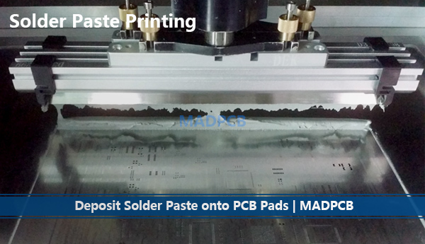
As a turnkey PCB assembler, MAD PCB uses automated solder paste printer and squeegee blade to spread the solder paste onto the circuit board. By dragging the squeegee blade across the stencil, customized as per IPC-7525A, they apply the pressure necessary to cover the circuit board evenly with the paste. The blades are usually constructed from metal. Here we list the most important factors that contribute to successful solder paste printing.
How to Guarantee Solder Paste Printing Quality?
- Squeegee Speed: The speed of travel of the squeeze determines how much time is available for the solder paste to “roll” into the apertures of the stencil and onto the pads of the PCB. Typically, a setting of 25mm per second is used but this is variable depending on the size of the apertures within the stencil and the solder paste used.
- Squeegee Pressure: During the print cycle, it is important to apply sufficient pressure across the entire length of the squeeze blade to ensure a clean wipe of the stencil. Too little pressure can cause “smearing” of the paste on the stencil, poor deposition, and the incomplete transfer to the PCB. Too much pressure can cause “scooping” of the paste from larger apertures, excess wear on the stencil and squeegees, and may cause “bleeding” of the paste between the stencil and PCB. A typical setting for the squeegee pressure is 500 grams of pressure per 25mm of squeegee blade.
- Squeeze Angle: The angle of the squeegee is typically set of 60° by the holders they are fixed to. If the angle is increased it can cause “scooping” of the holder paste from the stencil apertures and so less solder paste to be deposited. If the angle is reduced, it can cause a residue of solder paste to be left on the stencil after the squeeze has completed a print.
- Stencil Separation Speed: This is the speed at which the PCB separates from the stencil after printing. A speed setting of up to 3mm per second should be used and is governed by the size of the apertures within the stencil. If this is too fast, it will cause the solder paste to not fully release from the apertures and the formation of high edges around the deposits, also known as “dog-ears”.
- Stencil Cleaning: The stencil must be cleaned regularly during use which can be done either manually or automatically. The automatic printing machine has a system that can be set to clean the stencil after a fixed number of prints using lint-free material applied with a cleaning chemical such as Isopropyl Alcohol (IPA). The system performs two functions, the first being the cleaning of the underside of the stencil to stop smudging, and the second is the cleaning of the apertures using vacuum to stop blockages.
- Stencil and Squeegee Condition: Both stencils and squeegees need to be carefully stored and maintained as any mechanical damage to either can lead to undesired results. Both should be checked before use and thoroughly cleaned after use, ideally using an automated cleaning system so that any solder paste residue is removed. If any damage is noticed to squeegee or stencils, they should be replaced to ensure a reliable and repeatable process.
- Print Stroke: This is the distance the squeegee travels across the stencil and is recommended to be a minimum of 20mm past the furthest aperture. The distance past the furthest aperture is important to allow enough space for the paste to roll on the return stroke as it is rolling of the solder paste bead that generates the downward force that drives the paste into the apertures.
Paste Type, Storage and Handling
Solder paste is essentially powdered solder suspended in a thick medium called flux. The flux acts as a temporary adhesive, holding the components in place until the soldering process melts the solder and forms the electrical and mechanical connection.
Solder paste is a “Thixotropic” material and requires energy to be applied in the form of printed head motion for it to change viscosity and flow evenly into the stencil apertures. A term often used is the “Rheology” of the solder paste which describes how the solder paste from a block when no energy is applied but changes to a more fluid material when energy is applied.
The correct type of solder paste should be selected based upon the size of the apertures within the stencil. The release from the apertures of the stencil is affected by the particle size within the selected solder paste. Below are the particle size available.
| Particle Size (μm -micron) |
Particle Type |
| 75-45 | 2 |
| 45-25 | 3 |
| 38-20 | 4 |
| 25-15 | 5 |
| 15-5 | 6 |
There is a “5 ball rule” which says ideally a minimum of 5 solder particles should span the width of the smallest aperture. Both Tin-lead and Lead-Free solder paste should be refrigerated while being stored to maintain its shelf life but must be brought to room temperature for a minimum of eight hours before use to maintain quality. The solder paste should be mixed before use to ensure even distribution of any separated material throughout the paste.
As a general rule, solder paste that has been in use for more than 8 hours should be disposed of. Solder paste which has been in use for up to 4 hours can be stored for up to 24 hours in a sealed container at a room temperature before being re-used. The working environment (ambient temperature and relative humidity) will affect the performance and so to be sure of the condition of the solder paste a simple coalescence test can be carried out.
Which Kind PCBs Can Be Printed?
No matter rigid, IMS, rigid-flex or flex PCB (refer to our PCB Manufacturing), if the PCB strength is inadequate to support PCB itself as absolute flat as requirement on the rails of the SMT lines, the PCB assembly manufacturer will ask to customize SMT carrier or carrier (made of Durostone). How many SMT cahttps://madpcb.com/smt-pallet/rrier need to make? It’s dependent on the PCB assembly quantities.
This is an important factor to ensure the PCB is held flat against the stencil during the printing process. If the PCB, no matter rigid, IMS, rigid-flex or flex, is not fully supported, it can lead to printing defects, such as a poor paste deposit and smudging. PCB supports are generally supplied with printing machines which are a fixed height and have programmable positions to ensure a consistent process. There are also adaptable PCB and are useful for double-sided assembly.
Printed Solder Paste Inspection (SPI)
The solder paste printing process is one of the most important parts of the surface mount assembly process. The earlier a defect is identified the less it will cost to correct – a useful rule to consider is that a fault identified after reflow will cost 10 times the amount to rework than that identified before reflow – a fault identified after test will cost a further 10 times more to rework. It is understood that the solder paste printing process presents far more opportunities for defects than any of the other individual Surface Mount Technology (SMT) Manufacturing Processes. In addition, transition to lead-free solder paste and use of miniature components, has increased the complexity of the printing process. It has been proven that the lead-free solder pastes do not spread or “wet” as well as tin lead solder pastes. In general, a more accurate printing process is required in a lead-free process. This has pushed the manufacturer to implement some type of post-print inspection. To verify the process, automatic solder paste inspection can be used to accurately check solder paste deposits. At MADPCB, we can detect some defects of printed solder paste, line insufficient deposits, excessive deposits, shape deformation, missing paste, paste offset, smearing, bridging and more.