Table of Contents
PCB Assembly Files Required
MADPCB has committed to one-stop PCB solution services covering manufacturing, assembly and design. Once your PCB design is ready, there are a few files that you need to export for PCB assembly manufacturing. For a turnkey assembly inquiry and manufacturing, we require a bill of materials (BOM), centroid data, and of course your PCB designs in either Gerber or ODB++ format. In addition to the files just mentioned, it will also be helpful to include any additional files such as fabrication drawings or assembly drawings, or any special instructions specific to the project. If your design is not fully completed, we do provide preliminary quotes based on early Gerber files. Here are details on export these files below.
1. Gerber or ODB++ Files
Gerber files are a set of files containing information about each layer of the PCB to be used for production, and always are compressed into a .zip/.rar file. Along with your Gerber files, be sure to also include the drill files and a board outline file. A drill file contains the location and size of all drill holes. There may be multiple drilling files, if blind and/or buried vias, and back drilling are required. While, when you PCB need special process, like cut-outs, castellation, edge plating, carbon ink, FPC stiffener(s), EMI shielding film, PSA tape bonding, you also need to provide related mechanical layer(s). Please be sure to include all layer files to ensure none of your requirements are missed.
We also accept ODB++ file to replace Gerber files. These files are typically generated in an archive and include all fabrication files together.
2. Centroid File
The centroid file, also known as Pick-and-Place or XY Coordinate file, contains surface mounting devices (SMDs) information about where each component is placed on the printed circuit board, such as X/Y position, rotation, layer, reference designator and the value/package. Some design software can automatically generate this file and some not, but you may need to modify the file and then generate the centroid file.
3. BOM
The BOM is a list of all the parts that will be populated on the PCB board. BOM format can be any of Excel chart. The BOM for full turnkey and partial turnkey service may request a few more information than the BOM for consigned/kitted service.
BOM for Full Turnkey and Partial Turnkey service includes
- Item# (if necessary)
- Reference Designator (required)
- Package (if necessary)
- Quantity Per Board (required)
- Description (if necessary)
- Manufacturer Part Number (required)
- Manufacturer (required, some manufacturers have same part numbers)
- Notes (if necessary)
While, the positions that are left unassembled, or DNI (Do Not Include) should be included in the BOM. This makes the inspection of the assembly easier in various stages. In order to minimize the possibility of an error, the rows can be highlighted for example using yellow color.
As the components sourcing and assembly program making are based primarily on the BOM, it is important to be as accurate and careful as possible when filling the data into the excel file.
4. Assembly Drawings
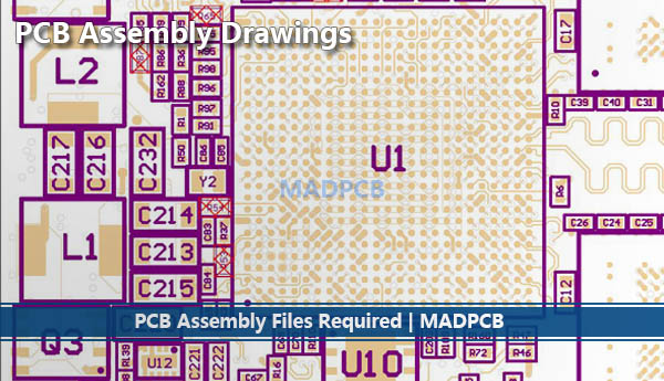
PCB Assembly Drawings
Like the PCB fabrication drawing, the assembly drawing is also typically auto-generated from the PCB design CAD tools. The purpose of the assembly drawing is to provide the assembly machine operator with enough information to check that the assembly rotation and polarity of each assembled component is correct and every component is on its correct position as specified by the designer, especially when no silkscreen printed on the printed circuit boards. At MADPCB, we prefer .pdf format. The drawing should clearly indicate pin 1 position of each IC and the reference designator of each component. Other types of common polarity markings are positive terminal marking for tantalum capacitors and cathode marking for diodes.
5. Others
You will also want to include some notes to instruct the PCB assembly provider on how the board is to be assembled. Depending on the complexity of the board though, there may be a lot more that needs to be included. Consider the following when you are creating your Assembly Drawing:
- Critical components, like connectors or heat sinks that need specialized mounting instructions, should be mentioned in the assembly notes on the drawing.
- Additional hardware that is to be mounted onto the board, such as stiffener bars, handles, or ejectors, should be shown with their specific instructions included in the drawing notes.
- Critical areas of assembly should have an explored view or “detail” shown that is enlarged and pulled away from the rest of the board image.
- The location of assembly stickers and label should also be shown on the drawing.