Table of Contents
Gerber File, Gerber Files, Gerber Format, Excellon and ODB++
What’s Gerber?
The Gerber format is an open 2D binary vector image format for PCB designs. It is the standard used by PCB industry software to describe the PCB images: copper layers, solder mask, silkscreen, outline and etc. are all represented by a flash or draw code, and defined by a series of vector coordinates. The files of all physical layers are in Gerber format, and we call any of them as Gerber file, and all of them as Gerber files.
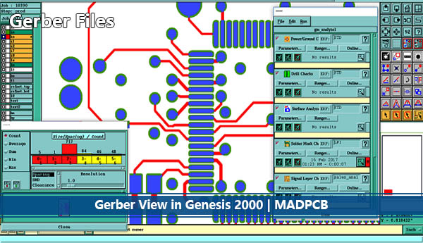
Gerber Files
Two Major Generations of Gerber Format
- Extended Gerber, or RS-274X is the current Gerber format. In 2014, the graphics format was extended with the option to add meta-information to the graphics objects. Files with attributes are called X2 files; those without attributes are X1 files.
- Standard Gerber, or RS-274D. This obsolete format was revoked.
The standard file extension is “.GBR” or “.gbr” though other extensions are also used.
Excellon Drilling File in Gerber
Gerber file is used in PCB fabrication data. PCBs are designed on a specialized EDA or a CAD system, like Dip Trace, Autodesk Eagle, KiCAD, Cadence OrCAD, pads and Altium Designer. The output PCB fabrication data to allow fabrication of the board. This data typically contains a Gerber file for each image layer and drill span (copper layers, solder mask, legend…) though for historic reasons the Excellon drill format is also sometimes used for drilled hole information. Typically, all these files are “zipped” into a single archive that is sent to the PCB fabricator. The fabricator input them into a CAM system to prepare data for each step of the PCB fabrication process.
Gerber file is also the standard image input format for all bare board fabrication equipment needing image data, such as photoplotters, silkscreen printers, direct imagers or AOI machines and for viewing reference images in different departments.
For PCB assembly, the fabrication data contains the solder paste layers and the central locations of components to create the SMD stencil, place and bond the components.
PCB Fabrication Data Rules
- Do not scale your data, and must be scale 1/1.
- No apertures with a zero-size, and Excellon data does not have zero sized tool.
- Use same offset for all Gerber layers and the Excellon file data. Preferably use no offset at all.
- Use the same units (mm or inch) in your Gerber & Excellon output files.
- Use the same resolution (grid) for your Gerber & Excellon data to allow a perfect match.
- Use flashed pads as often as possible in your Gerber files. (Recommendation)
- A board profile layer must be included.
- All layers must be aligned.
Gerber Extensions
| Extension | Description |
| .APR | Aperture File |
| .APT | Aperture File |
| .EXTREP | Extension Report of Gerber Files |
| .REP | Report of Individual Layer Used Aperture List |
| .RUL | DRC Rules |
| .GKO | Keep Out Layer |
| .GTO | Top Overlay |
| .GBO | Bottom Overlay |
| .GPT | Pad Master Top |
| .GPB | Pad Master Bottom |
| .GTS | Top Solder |
| .GBS | Bottom Solder |
| .GTL | Top Layer |
| .GBL | Bottom Layer |
| .GTP | Top Paste |
| .GBP | Bottom Paste |
| .G1, .G2, etc. | Mid-layer 1, 2, etc. |
| .GP1, .GP2, etc. | Internal Plane Layer 1, 2, etc. |
| .P01, .P02, etc. | Gerber Panels |
| .GM1, .GM2, etc. | Mechanical Layer 1, 2, etc. |
| .GD1, .GD2, etc. | Drill Drawing |
| .GG1, .GG2, etc. | Drill Guide |
| .DRL | Drill Data |
| .TXT | Drill Position |
| .DRR | Drill Tool Size |
| .LDP | Layer Pairs Export File for PCB |
ODB++
ODB++ is a proprietary CAD-to-CAM data exchange format. Except for Gerber files, ODB++ file is also acceptable for us to manufacture bare PCB.