Table of Contents
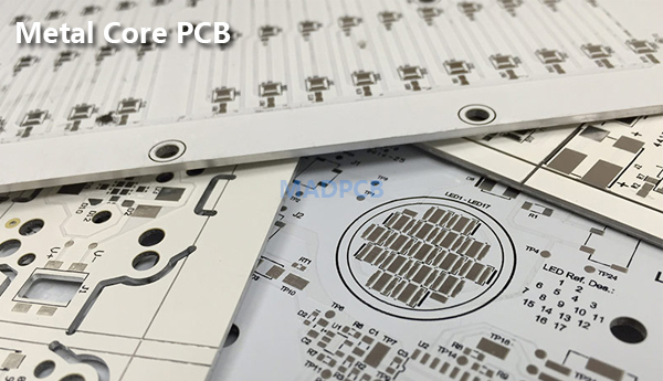
Metal Core PCB (MCPCB) | IMS PCB | Thermal PCB
Metal Core PCB, MCPCB, or sometimes Thermal PCB is a technology developed to overcome the thermal limitations of the FR-4 material. Metal core can be Aluminum (or Aluminium), or Copper, which is a better choice than FR4, if your PCB boards need to work in high temperature environment. There is a dielectric layer in-between copper foil and metal core for electric isolation. The special dielectric features with the peculiarity of having high thermal conductivity. Thus, metal core PCB substrate is also called as Insulated Metal Substrate (IMS). IMS PCBs or Metal Core PCBs are known for their ability to provide effective thermal dissipation for electronic products.
Metal Core PCB MCPCB
What is a Metal Core PCB?
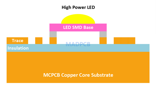
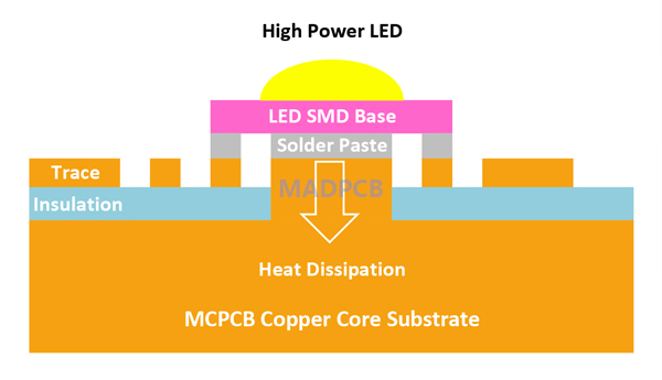
MCPCB is a type of PCB that has a metal material as its base for the heat spreader portion of the board. MCPCB consists of a thermal insulating layer (also called IMS layer), a metal plate and a copper foil, which has special magnetic conductivity, excellent heat dissipation, high mechanic strength and good processing properties. The purpose of the core of an MCPCB is to redirect heat away from critical PCB components and to less crucial areas such as the metal heatsink backing or metallic core. Common base materials of metal core PCBs are Aluminum, Copper or a mixture of special metal alloys. The chart below lists two common metal core material, MCPCB types, metal core thickness and copper thickness.
| Metal Core Material | MCPCB Type | Metal Core Thickness | Copper Thickness |
| Aluminum | Aluminum Core PCB | 0.75mm (30mil)-3.2mm(125mil) thicker or thinner are possible |
1-2oz thicker is possible |
| Copper | Copper Core PCB | 0.75mm (30mil)-3.2mm(125mil) thicker or thinner are possible |
1-10oz thicker is possible |
Copper core PCB has better performance than Aluminum PCB, but its price is relatively more expensive than aluminum core PCB. You can image it when you know the copper price is higher. Customers order Aluminum PCBs more often, because the price of aluminum PCB is much cheaper. A famous MCPCB application is Thermoelectric Separation, we call it as Thermoelectric Separated MCPCB. We can compare them with below images.
Standard Copper Core MCPCB
Copper Bumps Thermoelectric Separated MCPCB
Advantages of Metal Core PCB
Insulated Metal Substrate Technology offers a great list of advantages when an application requires great heat dissipation. Most engineers and designers rely on metal core PCB board to take its advantages compared to FR4 PCBs:
- Able to integrate a dielectric polymer layer with a high thermal conductivity for a lower thermal resistance.
- Able to transfer heat 8 to 9 times faster than FR4 PCBs.
- Able to dissipate heat, keeping heat generating components cooler which results in increased performance and life.
Metal Core PCB Applications
Printed circuit boards that require a lot of power usually generate a lot of heat at the same time. If your circuit boards need fast cooling, it is better to use metal core PCB. The following list includes some of the most popular applications that work great with this metal core technology.
- LED Lighting
- Power Conversion Systems
- Power Supplies
- Photovoltaics
- Telecom & Industrial
- Automobile Electronics
Typical Thermal Conductivity of Metal Core
| Material | Thermal Conductivity |
| Copper | 380 W/m·K |
| Aluminum | 140 – 220 W/m·K |
| Prepreg | 1 – 8 W/m·K |
Metal Core PCB Design Guidelines
Here are some MCPCB design guidelines for reference, including NPTH Drills, 1 Layer Metal Core and 2 Layers Metal Core PCBs.
- NPTH Drills
| MCPCB Thickness | Min. Drill Diameter |
| 0.5mm Metal core | 0.7mm (or 0.5mm) |
| 0.8mm Metal core | 0.7mm |
| 1.0mm Metal core | 0.8mm |
| 1.5mm Metal core | 0.9mm |
| 2.0mm Metal core | 1.0mm |
- Single-Sided Metal Core PCB Design
| Capability | 35µm Cu | 70µm Cu |
| Min Trace Width | 150µm | 200µm |
| Min Trace Spacing | 150µm | 200µm |
| Min Annular Ring | 125µm | 200µm |
| Min Drill (NPTH) | 0.7mm | 0.7mm |
| Min Drill Spacing | 250µm | 250µm |
- Double-Sided Metal Core PCB Design with PTHs
| Capability | 35µm Cu | 70µm Cu |
| Min Trace Width | 150µm | 200µm |
| Min Trace Spacing | 150µm | 200µm |
| Min Annular Ring | 125µm | 200µm |
| Min Drill (NPTH) | 0.7mm | 0.7mm |
| Min Via (PTH) | 0.3mm | 0.3mm |
| Min Drill Spacing | 250µm | 250µm |
| Min Via Spacing | 300µm | 300µm |
| Aspect Ratio | 10:01 | 10:01 |
Double-sided Metal Core PCB (MCPCB) Manufacturing Process
- Laminate Cutting: Cut a single-sided MCPCB laminate as per panel size.
- 1st Drilling: Drill larger holes (generally 1mm larger) in the same locations of PTHs required.
- Filled With Resin: Fully fill the drilled holes with resin to isolate the electrical connection between outer layers to the metal core.
- Laminate Pre-treatment: Abrading the back side of the metal core to get enough roughness to bonding a copper foil with PP.
- Lamination: Press and laminate copper foil (one sheet), PP (dielectric layer) and the single-sided CCL prepared in last process together to form a double-sided MCPCB laminate.
- 2nd Drilling: Drill holes (later to form PTHs) in the same locations as the 1st drilling but on cured resin.
Afterwards processes are the same as a double-sided PCB manufacturing. A double-sided MCPCB, copper core and aluminum core PCB manufacturing is more complex than a conventional circuit board with same layer count. MADPCB is a reliable MCPCB manufacturer, is capable of to be your one-stop PCB solution supplier to custom MCPCB design, fabrication and assembly, supports MCPCB prototype and production.