What Is Thermal Resistance in PCB?
Thermal Resistance in printed circuit board (PCB) is a physical quantity and the reciprocal of the thermal conductivity (Er or Dk). The primary parameter that determines how well your board distributes and dissipates heat is PCB thermal resistance. As excessive heat may cause damage to your circuit board during operation, it is critical that you employ good thermal design to avoid costly redesign and turnaround delays. For heat-critical projects you may possibly need the total thermal resistance of your metal core PCBs., like Aluminum PCB.
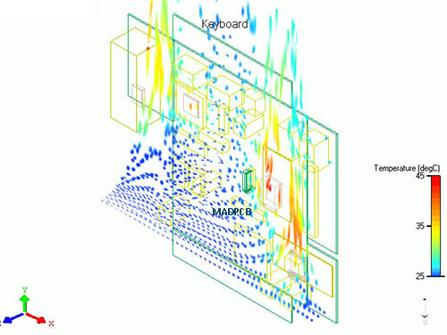
Thermal Simulation
You may probably familiar with the terms Thermal Pad, Thermal Relief Pad or Thermal Via. These all refer to connections to a copper plane (or pour) and impact thermal resistance. However, thermal relief pads are intended to evenly distribute to achieve a constant temperature and aid the reflow soldering process, while thermal vias are intended to dissipate heat away from components. Thermal relief and via locations are determined by heat distribution and dissipation concerns. This contrasts with component or footprint pad layouts that are based on design preferences and DFM rules for your PCB supplier, such as spacing and clearances.
Thermal reliefs also differ in primary function from other heat dissipation elements like heat sinks, which are intended for operational usage. Reliefs are intended to aid in board manufacturing, specifically printed circuit board assembly (PCBA) during the soldering of component steps. As such, they should be an essential part of your design for assembly (DFA) plan.
Importance of PCB Thermal Resistance
PCB thermal resistance may be broadly defined as the inverse of the board’s thermal conductivity, which along pure (≈100% Cu) copper through holes is 386W/m·K. To find the total thermal resistance for your circuit board, you must include all layers of the board and the associated heat parameters for the type of material through which heat will flow. There are several ways to determine your PCB thermal resistance explicitly; however, these can be quite cumbersome and are best performed with thermal analysis software.
For Thermal Vias
Resistance for thermal vias may be estimated as opposed to directly determined, using a calculator. For most PCB thermal resistance calculations, you will need to know the following:
- Trace (copper) thickness and thermal resistivity
- Laminate (insulation) thickness and thermal resistivity
- Substrate (core) thickness and thermal resistivity
With these parameters, you can estimate the PCB thermal resistance along any path by simply summing the values for the material(s) along the trace path.
For Component Packages
Another important thermal consideration is the dissipation of heat from component packages. Some high heat or high-power components utilize heat sinks to conduct heat away from the component into the surrounding air. These devices are most effective for operation and it is advisable to take into account component’s dissipation during reflow, where temperature variations of up to 80°C or more may be created across the board. Temperature change is proportional to change in resistance, as shown below.
∆R / R0 = α∆T
Where ∆R is the change in resistance
R0 is the reference resistance at ambient temperature
a is the temperature coefficient (0.0038/°C for copper)
∆T is the change in temperature from the ambient temperature
For traces and components, the lower the PCB thermal resistance, the better the heat dissipation.
3 Tips to Manage PCB Thermal Resistance for Manufacturing
- Choose materials and components based on their temperature coefficients: The amount of PCB thermal resistance for your traces and components depends on the properties of the PCB base materials and components that you select. Therefore, the first step in managing the resistances on your board is to make selections with favorable resistance and temperature parameters. For example, the most used PCB material, FR-4, is a good insulator, which means it has a high PCB thermal dissipation. As such, it is not the best choice to relieve high heat concentrations on your board.
- Space high power components away from each other: Components that tend to generate high heat should be sparsely placed on your board, as much as possible. This placement helps minimize high-temperature concentrations that are more likely to be problematic during PCB assembly reflow.
- Make good use of thermal vias to improve dissipation: For surface mount devices (SMDs), use vias liberally to remove heat from high power components. Through-hole vias have good thermal dissipation properties and can be used to quickly remove from components and the board surface.
Employing the tips above during your PCB design will improve the heat distribution and dissipation of your board. By keeping PCB thermal resistance manageable, you can facilitate smooth PCB assembly and preserve the integrity of your circuit boards.