What’s PLCC Package?
Plastic Leaded Chip Carrier (PLCC) is a four-sided plastic SMT chip package that has “J” leads around its periphery. These “J” leads occupy less board space than the gull-wing leads that other packages like the SOIC have. It is a reduced cost evolution of the ceramic leadless chip carrier (CLCC).
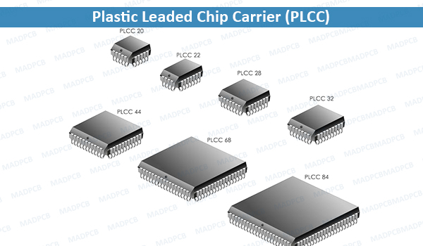
Plastic Leaded Chip Carrier (PLCC)
The body widths range from .35″to 1.15″. PLCCs have JEDEC-standard package outlines. The standard lead pitch is 1.27 mm. It must not be confused with the LCC, which is a leadless and more expensive ceramic package. The leads are spaced at .05”, so this package is not considered fine-pitch. Also see Chip Carrier. The lead counts range from 18 to 84. The packages can either be square or rectangular in shape. The ceramic equivalent is the JLCC.
| Properties of Some Examples | ||
| Part Number | Pin Count | Body Size |
| PLCC20 | 20 | 8.8mm |
| PLCC28 | 28 | 11.4mm |
| PLCC32 | 32 | 11.4mm |
| PLCC44 | 44 | 16.5mm |
| PLCC52 | 52 | 19.0mm |
| PLCC68 | 68 | 24.1mm |
| PLCC84 | 84 | 29.2mm |
A premolded PLCC was originally released in 1976, but did not see much market adoption. Texas Instruments later released a postmolded variant that was soon adopted by most major semiconductor companies. The JEDEC trade group started a task force in 1981 to categorize PLCCs, with the MO-047 standard released in 1984 for square packages and the MO-052 standard released in 1985 for rectangular packages.
The PLCC utilizes a “J”-lead with pin spacings of 0.05″ (1.27 mm). The metal strip forming the lead is wrapped around and under the edge of the package, resembling the letter J in cross-section. Lead counts range from 20 to 84. PLCC packages can be square or rectangular. Body widths range from 0.35″ to 1.15″. The PLCC “J” Lead configuration requires less board space versus equivalent gull leaded components, which have flat leads that extend out perpendicularly to the narrow edge of the package. The PLCC is preferred over DIP style chip carriers when lead counts exceed 40 pins due to the PLCC’s more efficient use of board surface area.
The heatspreader versions are identical in form factor to the standard non-heatspreader versions. Both versions are JEDEC compliant in all respects. The heatspreader versions give the system designer greater latitude in thermally-enhanced board level and/or system design. RoHS compliant, lead-free and green material sets are now qualified standards.
A PLCC circuit may either be installed in a PLCC socket or surface-mounted. PLCC sockets may in turn be surface mounted, or use through-hole technology. The motivation for a surface-mount PLCC socket would be when working with devices that cannot withstand the heat involved during the reflow process, or to allow for component replacement without reworking. Using a PLCC socket may be necessary in situations where the device requires stand-alone programming, such as some flash memory devices. Some through-hole sockets are designed for prototyping with wire wrapping.
PLCCs continue to be used for a wide variety of device types, which would include memory, processors, controllers, ASICs, DSPs, etc. It is particularly common for read-only memories, as it provides an easily swappable socketed chip. Applications range from consumer products through automotive and aerospace.