What Is a Resistor Color Code?
A Resistor Color Code is used to indicate the values or functions of resistors. Resistor Color Coding uses colored bands to quickly identify a resistors resistive value and its percentage of tolerance with the physical size of the resistor indicating its wattage rating.
How Does the Resistor Color Code Work?
Resistor values are often indicated with color codes. Practically all leaded resistors with a power rating up to one watt are marked with color bands. The coding is defined in the international standard IEC 60062. This standard describes the marking codes for resistors and capacitors. In addition to defining the color bands, the standard also includes numerical codes, as often used for surface mount SMD resistors.
The color code is given by several bands. Together they specify the resistance value, the tolerance, and sometimes the reliability or failure rate. The number of bands varies from three to six. At a minimum, two bands indicate the resistance value and one band serves as multiplier. The resistance values are standardized; these values are called preferred values.
History
Before industry standards were established, each manufacturer used their own unique system for color coding or marking their components.
In the 1920s, the RMA resistor code was developed by the Radio Manufacturers Association (RMA) as a fixed resistor coloring code marking. In 1930, the first radios with RMA color-coded resistors were built. Over many decades, as the organization name changed (RMA, RTMA, RETMA, EIA) so was the name of the code. Through known most recently as EIA color code, the four name variations are found in books, magazines, catalogs, and other documents over more than 91 years.
In 1952, it was standardized in IEC 62:1952 by IEC and since 1963 also published as EIA RS-279. Originally only meant to be used for fixed resistors, the color code was extended to also cover capacitors with IEC 62:1968. The code was adopted by many national standards like DIN 40825 (1973), BS 1852 (1974) and IS 8186 (1976). The current international standard defining marking codes for resistors and capacitors in IEC 60062:2016 and EN 60062:2016. In addition to the color code, these standards define a letter and digit code named RKM code for resistors and capacitors.
Color bands were used because they were easily and cheaply printed on tiny components. However, there were drawbacks, especially for color blind people. Overheating of a component or dirt accumulation may make it impossible to distinguish brown from red or orange. Advances in printing technology have now made printed numbers more practical on small components. The values of components in surface mount packages are marked with printed alphanumeric codes instead of a color code.
Resistor Color Code Chart
The chart below shows how to determine the resistance and tolerance for resistors. The table can also be used to specify the color of the bands when the values are known. An automatic resistor calculator can be used to quickly find the resistor values.
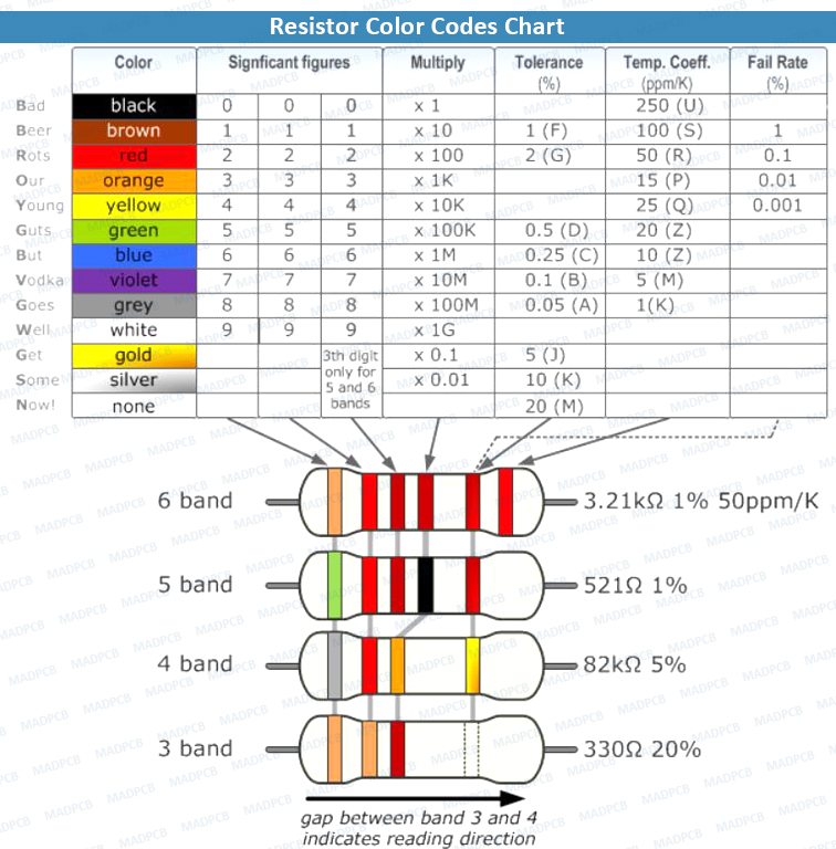
Resistor Color Codes Chart
Tips for Reading Resistor Codes
In the sections below, examples are given for different numbers of color bands. But, first, here are some general tips for reading the color code:
- The reading direction might not always be clear. Sometimes the increased space between bands 3 and 4 provide an indication of the reading direction. Also, the first band is usually the closest to a lead. A gold or silver band (the tolerance) is always the last band.
- It is a good practice to check the manufacturer’s documentation to be sure about the color coding system used.
- When in doubt, measure the resistance with a ohmmeter. In some cases, this might even be the only way to figure out the resistance; for example, when the color bands are burnt off.
4 Band Resistor
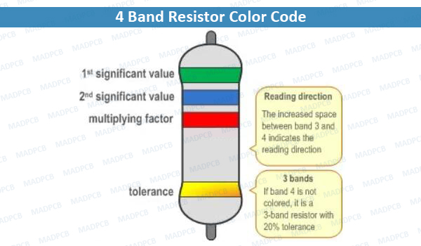
4 Band Resistor Color Code
The four (4) band color code is the most common variation. These resistors have two bands for the resistance value, one multiplier and one tolerance band. In the example shown here, the 4 bands are green, blue, red and gold. By using the color code chart, one finds that green stands for 5 and blue for 6. The third band is the multiplier, with red representing a multiplier value of 2 (102). Therefore, the value of this resistor is 56 · 102 = 56 · 100 = 5600 Ω. The gold band means that the resistor has a tolerance of 5%. The resistance value lies therefore between 5320 and 5880 Ω (5560 ± 5%). If the tolerance band is left blank, the result is a three (3) band resistor. This means that the resistance value remains the same, but the tolerance is 20%.
5 Band Resistor
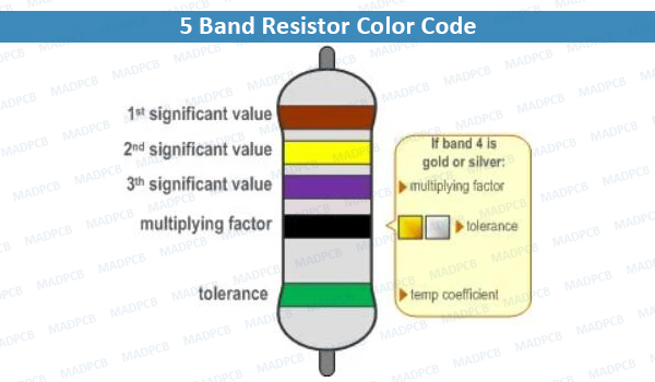
5 Band Resistor Color Code
Resistors with high precision have an extra band to indicate a third significant digit. Therefore, the first three bands indicate the significant digits, the fourth band is the multiplication factor, and the fifth band represents the tolerance. For the example shown here: brown (1), yellow (4), violet (7), black (x 100 = x1), green (0.5%) represents a 147 Ω resistor with a 0.5% tolerance.
There are exceptions to this 5-band color system. For example, sometimes the extra band may indicate failure rate (military specification) or temperature coefficient (older or specialized resistors). Please read the subsection “Color Code Exceptions” below for more information.
6 Band Resistor
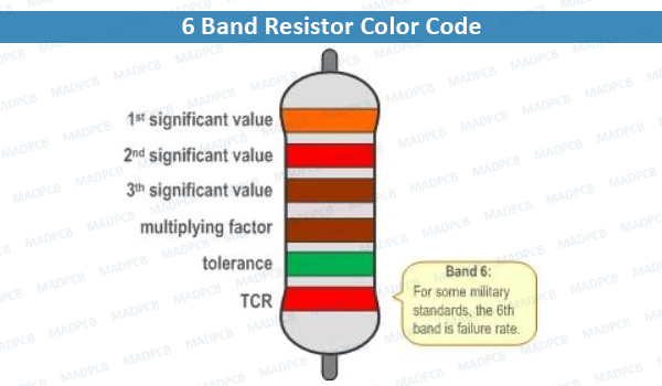
6 Band Resistor Color Code
Resistors with 6 bands are usually for high precision resistors that have an additional band to specify the temperature coefficient (ppm/˚C = ppm/K). The most common color for the sixth band is brown (100 ppm/˚C). This means that for a temperature change of 10 ˚C, the resistance value can change 1000 ppm = 0.1%. For the 6 band resistor example shown above: orange (3), red (2), brown (1), brown (x10), green (1%), red (50 ppm/°C) represents a 3.21 kΩ resistor with a 1% tolerance and a 50 ppm/°C temperature coefficient.
Color Code Exceptions
The color coded resistors are inserted in circuit boards, and the PCB assembly manufacturing is finished by thru-hole pin soldering.
- Reliability band: Resistors that are produced according to military specifications, sometimes include an extra band to indicate reliability. This is specified in failure rate (%) per 1000 hours of service. This is rarely used in commercial electronics. Most often the reliability band can be found on four band resistors. More information about the reliability can be found in the US military handbook MIL-HDBK-199.
- Single black band or zero-ohm resistor: A resistor with a single black band is called a zero-ohm resistor. Principally, it is used as a wire link that functions to connect traces on a printed circuit board (PCB). Using the resistor package allows the same automated pick-and-place machines to place the components on a circuit board.
- 5 band resistor with a 4th band of gold or silver: Five band resistors with a fourth band of gold or silver form an exception and are used on specialized and older resistors. The first two bands represent the significant digits, the 3rd is the multiplication factor, the 4th is the tolerance, and the 5th is the temperature coefficient (ppm/˚C).
- Deviating colors: For high voltage resistors, the colors gold and silver are often replaced with yellow and gray. This is to prevent having metal particles in the coating.