What Is A Silicon Controlled Rectifier?
A Silicon Controlled Rectifier (SCR) is a four-layer solid-state current-controlling silicon device. The principle of four-layer P-N-P-N switching was developed in 1956. The practical demonstration of SCR and detailed theoretical behavior of a device is agreement with the experimental results was presented in 1958. The SCR was developed by a team of power engineers in 1957. Also see SCS.
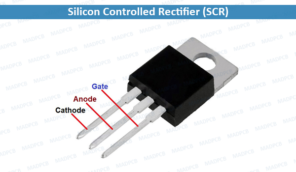
Silicon Controlled Rectifier (SCR)
Some sources define silicon-controlled rectifiers and thyristors as synonymous while other sources define them as a proper subset of the set of thyristors; the latter being devices with at least four layers of alternating n- and p- type material. According to Bill Gutzwiller, the term “SCR” and “controlled rectifier” were earlier, and “thyristor” was applied later, as usage of the device spread internationally.
SCRs are unidirectional devices (i.e. can conduct current only in one direction) as opposed to TRIACs, which are bidirectional (i.e. charge carriers can flow through them in either direction). SCRs can be triggered normally only by a positive current going into the gate as opposed to TRIACs, which can be triggered normally by either a positive or a negative current applied to its gate electrode.
Modes of Operation
There are three modes of operation for an SCR depending upon the biasing given to it:
- Forward blocking mode (off gate): the anode (+) is given a positive voltage while the cathode (-) is given a negative voltage, keeping the gate at zero (0) potential i.e. disconnected. In this case junction J1 and J3 are forward-biased, while J2 is reverse-biased, allowing only a small leakage current from anode to the cathode. When the applied voltage reaches the breakover value for J2, then J2 undergoes avalanche breakdown. At this breakover voltage J2 starts conducting, but below breakover voltage J2 offers very high resistance to the current and the SCR is said to be in the off state.
- Forward conduction mode (on state): An SCR can be brought from blocking mode to conduction mode in two ways: Either by increasing the voltage between anode and cathode beyond the breakover voltage, or by applying a positive pulse at the gate. Once the SCR starts conducting, no more gate voltage is required to maintain it in the ON state. The minimum current necessary to maintain the SCR in the ON state on removal of the gate voltage is called the latching current. There are two ways to turn it off:
- Reduce the current through it below a minimum value called the holding current, or
- With the gate turned off, short-circuit the anode and cathode momentarily with a push-button switch or transistor across the junction.
- Reverse blocking mode (off state): When a negative voltage is applied to the anode and a positive voltage to the cathode, the SCR is in reverse blocking mode, making J1 and J3 reverse biased and J2 forward biased. The device behaves as two diodes connected in series. A small leakage current flows. This is the reverse blocking mode. If the reverse voltage is increased, then at critical breakdown level, called the reverse breakdown voltage (VBR), an avalanche occurs at J1 and J3 and the reverse current increases rapidly. SCRs are available with reverse blocking capability, which adds to the forward voltage drop because of the need to have a long, low-doped P1 region. Usually, the reverse blocking voltage rating and forward blocking voltage rating are the same. The typical application for a reverse blocking SCR is in current-source inverters. An SCR incapable of blocking reverse voltage is known as an asymmetrical SCR, abbreviated ASCR. It typically has a reverse breakdown rating in the tens of volts. ASCRs are used where either a reverse conducting diode is applied in parallel (for example, in voltage-source inverters) or where reverse voltage would never occur (for example, in switching power supplies or DC traction choppers). Asymmetrical SCRs can be fabricated with a reverse conducting diode in the same package. These are known as RCTs, for reverse conducting thyristors.