What’s Strain Relief in Flex PCB?
For rigid-flex PCBs, and flexible printed circuits (FPCs) with stiffeners, the space connecting rigid material to flex material is called Transition Zone, Transition Area, Transition Line, Transition Interface, or Seam. Rigid material commonly includes CCL, PP, and rigid (FR-4, stainless steel, or Aluminum) stiffeners. Flex material includes FCCL and coverlay. The transition zone is a very sensitive area that must be built with much care, or the transition zone may be damaged if bend.
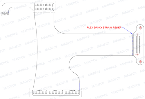
Strain Relief, also called Bend Relief, as the name implies, relieves the strain that could damage the transition zone when bending at the transition zone.
Strain Relief in PCB
In PCB manufacturing, the transition zone sometimes happens to imperfections, although acceptable, could impact effectiveness of the final product. The imperfections can include any of the following:
- Bonding sheet squeeze-out
- Protruding epoxy resin from PP
- Cracking
- Haloing
If the parts are bended at the interface, the remaining cured adhesive could damage the underlying flexible laminate. To protect the underlying flexible laminate, flex PCB designers require a strain relief adhesive in the transition zone. The applied, cured adhesive will help to extend the bending area past the remaining cured resin.
Strain Relief Fillet
A Strain Relief Fillet is defined as a Flexible Bead or Strain Relief Adhesive, applied to the transition line from a rigid area to a flex area. This forces the flex to bend gradually and prevents it from being bent tightly against the rigid area which could damage the part. It refers to a bead of semi-rigid adhesive applied along transitions that can reduce, or eliminate, stress concentration features.
There are two kinds of non-conductive strain relief adhesives commonly used in flex PCB manufacturing, including
- RTV Silicon: RTV is shortened from Room Temperature Vulcanizing. It is available as a one-component product, or mixed from two-components (a base and curative). It is a type of silicone rubber that cures at room temperature.
- Eccobond 45: Now it is called LOCTITE ABLESTIK 45, which is an epoxy based adhesive. When mixing component A (black resin) and component B (black hardener) through different mixing ratio, the cured adhesive has different flexibility. Under 105°C curing temperature, it requires 15 to 30 minutes to be cured. But considering its price, most PCB fabricators use alternative epoxy resin adhesive to replace it.
In PCB manufacturing, epoxy resin adhesive is more widely used than RTV, and almost no one even wants to use RTV. That’s because epoxy resin adhesive has much better flexibility.
How to Apply Strain Relief Adhesive?
When flex PCB is finished, the last process is to apply adhesive. Approaches include by hand through a syringe filling, and by machine through automated filling. Here is a video showing how a machine automate fill strain relief adhesive onto the transition zones.
IPC called out for a minimum 10mil (0.25mm) height difference of strain relief adhesive between the rigid area and the flex layers to allow enough space for the bead without it extending above the surface level of the rigid area. Strain reliefs requirements are defined in the fabrication drawing. A minimum and maximum horizontal dimension need to be defined as is commonly 40mil (1.0mm) to 100mil (2.5mm) to allow for manufacturing tolerances and the material flow properties. Others can be used but will need to be applied after assembly if they cannot withstand assembly reflow soldering temperatures.
Many designs do not require or cannot utilize strain reliefs. Epoxy strain reliefs are an optional feature that may be required to ensure bend reliability. This extra process will increase your PCB cost upon epoxy fillet usage volume, labor and time. Designs with very short flex lengths may result in the strain reliefs limiting the bend capabilities. The added cost may not be justified for relaxed bend applications. Reliefs should also be limited to the rigid to flex transitions that require it and not applied globally.
When designing strain relief into your flexible circuits that you refer to IPC-2223, section 5.2.9 for complete guidelines and limitations. A properly designed strain relief will prevent conductor strains when bent near the rigid to flex transition areas.