What’s Thermal Stability in PCB?
A Tantalum Capacitor or Tantalum Electrolytic Capacitor is an electrolytic capacitor, a passive component of electronic circuits. It consists of a pellet of porous tantalum metal as an anode, covered by an insulating oxide layer that forms the dielectric, surrounded by liquid or solid electrolyte as a cathode. Because of its very thin and relatively high permittivity dielectric layer, the tantalum capacitor distinguishes itself from other conventional and electrolytic capacitors in having high capacitance per volume (high volumetric efficiency) and lower weight.
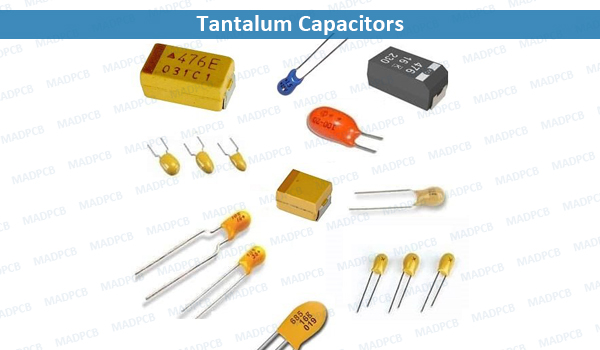
Tantalum Capacitors
Tantalum is a conflict mineral. Tantalum electrolytic capacitors are considerably more expensive than comparable aluminum electrolytic capacitors. Tantalum capacitors are inherently polarized components. Reverse voltage can destroy the capacitor. Non-polar or bipolar tantalum capacitors are made by effectively connecting two polarized capacitors in series, with the anodes oriented in opposite directions.
Why Use Tantalum Capacitors in Your PCB Design?
The tantalum capacitor has excellent stability characteristics. Across a wide range of temperatures and frequencies, the tantalum capacitor will maintain the expected capacitance better. With this stability you get more of the expected behavior of your PCB design, which is especially important for filters; if the capacitance varies too much you may lose frequencies you desire. Beyond the electrical differences the construction of the tantalum capacitor also makes it highly resistant to vibration issues, improving overall system reliability.
The previous characteristics show how tantalum capacitors can be uniquely suited to help in modern electronics, but they are not without their quirks and there are a couple of major ones to take into account when you want to design these in. Tantalum capacitors are generally polarized devices, meaning that during PCB layout and PCB assembly, you need to pay more attention to their orientation. This makes them a little more work than a regular ceramic capacitor, which is just a trait of electrolyte base capacitors. When putting tantalum capacitors into a board, you also need to watch out for their failure modes.
Leaded Tantalum Capacitors
Leaded tantalum capacitors typically come in a small and encapsulated in epoxy package to prevent damage. In view of their shape, they are sometimes referred to as tantalum bead capacitors. The capacitor marking are normally written directly onto the encapsulation, although a color coding system was popular at one time and some capacitors may still be seen using this system.
SMD Tantalum Capacitors
Surface mount tantalum capacitors are widely used in modern electronics equipment. When designed with sufficient margins, they provide reliable service and enable high values of capacitance to be obtained within the small package sizes needed for modern equipment.
Aluminum electrolytic types were not initially available in surface mount packages as they were not able to withstand the temperatures needed in soldering. As a result, tantalum capacitors which were able to withstand the reflow soldering process were almost the only choice for high value capacitors in assemblies using surface mount technology (SMT). Now that SMD types are available, tantalum is still the capacitor of choice for SMD as they offer an excellent cost, size and performance parameters.
SMD tantalum capacitors come in a variety of sizes. Typically they conform to standard sizes defined by the EIA.
| Surface Mount Tantalum Capacitor Size | ||
| Designation | Size (mm) | EIA Designation |
| Size A | L3.2 x W1.6 x H1.6 | EIA 3216-18 |
| Size B | L3.5 x W2.8 x H1.9 | EIA 3528-21 |
| Size C | L6.0 x W3.2 x H2.2 | EIA 6032-28 |
| Size D | L7.3 x W4.3 x H2.4 | EIA 7343-31 |
| Size E | L7.3 x W4.3 x H4.1 | EIA 7343-43 |
The markings on SMD types normally consist of three numbers. The first two form the significant figures, and the third is the multiplier. Values are in picofarads (pF). For example, 495E, it means 4.9x10⁵pF, which works out to be 4.9μF. Sometimes values will be marked more directly with value and unit.
Summary
The table below provides some of the salient features about tantalum capacitors to take into consideration when designing circuits or replacing old components.
| Parameter | Details |
| Typical capacitance ranges | 1μF to 100μF |
| Rated voltage availability | From around 1.5V to 20V |
| Advantages |
|
| Disadvantages |
|