What’s Voltage Divider?
In electronics, a Voltage Divider (also known as a Potential Divider) is a passive linear circuit that produces an output voltage (Vout) that is a fraction of its input voltage (Vin). Voltage division is the result of distributing the input voltage among the components of the divider. A simple example is two resistors connected in series, with the input voltage applied across the resistor pair and the output voltage emerging from the connection between them.
In a word, it is a simple circuit which turns a large voltage into a smaller one. Using just two series resistors and an input voltage, we can create an output voltage that is a fraction of the input.
Resistor-voltage-dividers are commonly used to create reference voltages, or to reduce the magnitude of a voltage so it can be measured, and may also be used as signal attenuators at low frequencies. For direct current and relatively low frequencies, it may be sufficiently accurate if made only of resistors; where frequency response over a wide range is required (such as in an oscilloscope probe), a voltage divider may have capacitive elements added to compensate load capacitance. In electric power transmission, a capacitive-voltage-divider is used for measurement of high voltage.
General Case
A voltage divider referenced to ground is created by connecting two electrical impedances in series, as shown in following figure. The input voltage is applied across the series impedances Z1 and Z2 and the output is the voltage across Z2. Z1 and Z2 may be composed of any combination of elements such as resistors, inductors and capacitors.
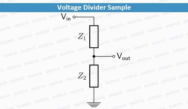
Voltage Divider Sample
If the current in the output wire is zero then the relationship between the input voltage, Vin, and the output voltage, Vout, is:
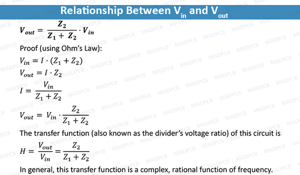
Relationship Between Vin and Vout
Applications
- Sensor measurement: used to allow a microcontroller to measure the resistance of a sensor. The sensor is wired in series with a known resistance to form a voltage divider and a known voltage is applied across the divider. The microcontroller’s analog-to-digital converter is connected to the center tap of the divider so that it can measure the tap voltage and, by using the measured voltage and the known resistance and voltage, compute the sensor resistance. An example that is commonly used involves a potentiometer (variable resistor) as one of the resistive elements. When the shaft of the potentiometer is rotated the resistance it produces either increases or decreases, the change in resistance corresponds to the angular change of the shaft. If coupled with a stable voltage reference, the output voltage can be fed into an analog-to-digital converter and a display can show the angle. Such circuits are commonly used in reading control knobs. Note that it is highly beneficial for the potentiometer to have a linear taper, as the microcontroller or other circuit reading the signal must otherwise correct for the non-linearity in its calculations.
- High voltage measurement: used to scale down a very high voltage so that it can be measured by a voltmeter. The high voltage is applied across the divider, and the divider output—which outputs a lower voltage that is within the meter’s input range—is measured by the meter. High voltage resistor divider probes designed specifically for this purpose can be used to measure voltages up to 100 kV. Special high-voltage resistors are used in such probes as they must be able to tolerate high input voltages and, to produce accurate results, must have matched temperature coefficients and very low voltage coefficients. Capacitive divider probes are typically used for voltages above 100 kV, as the heat caused by power losses in resistor divider probes at such high voltages could be excessive.
- Logic level shifting: used as a crude logic level shifter to interface two circuits that use different operating voltages. For example, some logic circuits operate at 5V whereas others operate at 3.3V. Directly interfacing a 5V logic output to a 3.3V input may cause permanent damage to the 3.3V circuit. In this case, a voltage divider with an output ratio of 3.3/5 might be used to reduce the 5V signal to 3.3V, to allow the circuits to interoperate without damaging the 3.3V circuit. For this to be feasible, the 5V source impedance and 3.3V input impedance must be negligible, or they must be constant and the divider resistor values must account for their impedances. If the input impedance is capacitive, a purely resistive divider will limit the data rate. This can be roughly overcome by adding a capacitor in series with the top resistor, to make both legs of the divider capacitive as well as resistive.