What’s Voltage Drop?
Voltage Drop is the decrease of electrical potential along the path of a current flowing in an electrical circuit. Voltage drops in the internal resistance of the source, across conductors, across contacts, and across connectors are undesirable because some of the energy supplied is dissipated. The voltage drop across the electrical load is proportional to the power available to be converted in that load to some other useful form of energy.
For example, an electric space heater may have a resistance of ten ohms, and the wires that supply it may have a resistance of 0.2 ohms, about 2% of the total circuit resistance. This means that approximately 2% of the supplied voltage is lost in the wire itself. An excessive voltage drop may result in the unsatisfactory performance of a space heater and overheating of the wires and connections.
National and local electrical codes may set guidelines for the maximum voltage drop allowed in electrical wiring to ensure efficiency of distribution and proper operation of electrical equipment. The maximum permitted voltage drop varies from one country to another. In electronic design and power transmission, various techniques are employed to compensate for the effect of the drop on long circuits or where voltage levels must be accurately maintained. The simplest way to reduce voltage drop is to increase the diameter of the conductor between the source and the load, which lowers the overall resistance. In power distribution systems, a given amount of power can be transmitted with less voltage drop if a higher voltage is used. More sophisticated techniques use active elements to compensate for excessive voltage drop.
Voltage Drop in DC Circuits: Resistance
Consider a direct-current circuit with a nine-volt DC source; three resistors of 67 ohms, 100 ohms, and 470 ohms; and a light bulb—all connected in series. The DC source, the conductors (wires), the resistors, and the light bulb (the load) all have resistance; all use and dissipate supplied energy to some degree. Their physical characteristics determine how much energy. For example, the DC resistance of a conductor depends upon the conductor’s length, cross-sectional area, type of material, and temperature.
If the voltage between the DC source and the first resistor (67 ohms) is measured, the voltage potential at the first resistor will be slightly less than nine volts. The current passes through the conductor (wire) from the DC source to the first resistor; as this occurs, some of the supplied energy is “lost” (unavailable to the load), due to the resistance of the conductor. Voltage drop exists in both the supply and return wires of a circuit. If the drop across each resistor is measured, the measurement will be a significant number. That represents the energy used by the resistor. The larger the resistor, the more energy used by that resistor, and the bigger the drop across that resistor.
Ohm’s Law can be used to verify voltage drop. In a DC circuit, voltage equals current multiplied by resistance. V = I R. Also, Kirchhoff’s circuit laws state that in any DC circuit, the sum of the drops across each component of the circuit is equal to the supply voltage.
Voltage Drop in AC Circuits: Impedance
In alternating-current circuits, opposition to current flow occurs because of resistance, just as in direct-current (DC) circuits. However, alternating current (AC) circuits also include a second kind of opposition to current flow: reactance. The sum of oppositions to current flow from both resistance and reactance is called impedance.
Electrical impedance is commonly represented by the variable Z and measured in ohms at a specific frequency. Electrical impedance is computed as the vector sum of electrical resistance, capacitive reactance, and inductive reactance.
The amount of impedance in an alternating-current circuit depends on the frequency of the alternating current and the magnetic permeability of electrical conductors and electrically isolated elements (including surrounding elements), which varies with their size and spacing.
Analogous to Ohm’s law for direct-current circuits, electrical impedance may be expressed by the formula E = I Z. So, the voltage drop in an AC circuit is the product of the current and the impedance of the circuit.
How to Solve Current and Voltage Drop on PCBs?
Electronic components on printed circuit boards (PCBs) operate with different supply voltages like 5V, 3.3V, 2.5V or less. The components work as specified when the supply voltage is stable within a given tolerance as specified in the datasheet i.e. +/- 10%. A voltage drop is called IR-drop on PCBs and happens, when a voltage is connected to the device pin with a trace or plane, which has an ohm resistance. If the trace or plane is thick and wide the resistance will be low. But when space on a PCB is limited, the track width is often small and supply planes have many wholes. In such a case there will be loss of voltage due to Ohm’s law. Energy is transformed from electrical energy into thermal energy and the value for the voltage goes down.
Vdrop = I * R (Vdrop is called IR-Drop)
P = I * Vdrop * R (P is the power converted from electrical to thermal energy)
With IR-drop analysis the PCB designer can see where a plane has too many wholes, a trace is to narrow and too long or there are not enough vias placed. In these cases, the voltage drops. The resistance can be calculated with a field solver and a simulation shows the results for
current, voltage drop and temperature increase.
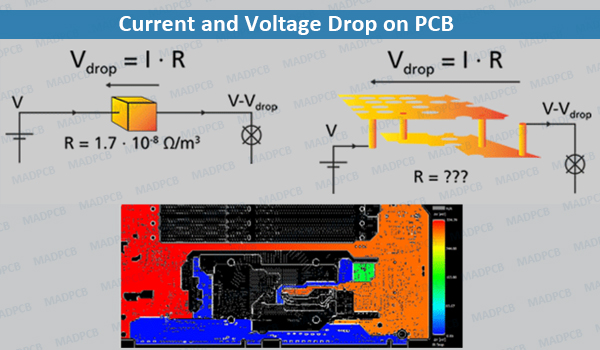
Current and Voltage Drop on PCB
Power / ground paths should have low resistance. The goal is to ensure that minimum power is dissipated as heat in the system. Each voltage drop will generate heat and might cause thermal issues with some components close by. When the voltage drops to much, the supply voltage might reach the lower tolerance of the supply voltage and the electronic components fail. Power integrity is an important consideration in advanced devices as it is deeply related to many signal integrity problems.