Reflow Soldering in PCB Assembly
Infra-Red (IR) Reflow Soldering is a SMT process in PCB assembly manufacturing, in which a solder paste is used to temporarily attach one or thousands of tiny SMD components to their contact pads on bare printed circuit board, after which the entire SMT assembly is subjected to controlled heat. The solder paste reflows in a molten state, creating permanent solder joints. In SMT house, the heating can be accomplished by passing the assembly through a reflow oven by soldering individual joints.
Preparation before Reflow Soldering
The first stage in reflow soldering for SMT assembly is to apply solder paste and place components to the printed circuit boards, which can be flex, rigid, metal core and rigid-flex.
- Solder Paste: In essence solder paste is applied to the board. The paste is only deposited to the contact pads that require soldering. While boards have solder resist (solder mask) layers added to them, it is necessary to only add solder paste to those areas where the solder is actually required. This is achieved by having a solder paste printer. This only allows the solder paste to be added to those areas of the board where it is needed. Once printed, the solder paste has been added to the board, it can move on to the next stage through SMT line rail.
- Pick and Place: With the solder paste on the board, the components can then be set in place. Normally, an automatic pick and place machine is used because the numbers of components used nowadays, the accuracy and turnaround required make manual placement non-viable. The pick and place machine places the SMD components onto the board, and they are held in place by the surface tension of the solder paste. This is quite sufficient for normal handling, although some care is obviously needed. It is possible for the components to be glued to the board, but this makes rework very difficult. Then with all the components in place they can be moved to the reflow soldering oven. The pick and place machine places the SMD components onto the board, and they are held in place by the surface tension of the solder paste. This is quite sufficient for normal handling, although some care is obviously needed. It is possible for the components to be glued to the board, but this makes rework very difficult. Then with all the components in place they can be moved to the reflow soldering oven.
- Thermal Profiling: After pick and place but before reflow soldering, we need to find the optimal thermal profile (or reflow soldering profile). Thermal profiling is the act of measuring several points on a circuit board to determine the thermal excursion it takes through the soldering process. In the electronics manufacturing industry, SPC (Statistical Process Control) helps determine if the process is in control, measured against the reflow parameters defined by the soldering technologies and component requirements. Modern software tools allow a profile to be captured, then automatically optimized using a mathematical simulation, which greatly reduced the time needed to establish optimal for the process.
Reflow Soldering Process
In nowadays PCB assembly, especially for high-volume production, reflow soldering is an extremely important step in SMT (Surface Mounting Technology) process. The temperature curve associated with the reflow is an essential parameter to control to ensure the correct connection of parts. The parameters of certain components will also directly impact the temperature curve selected for this step in the process.
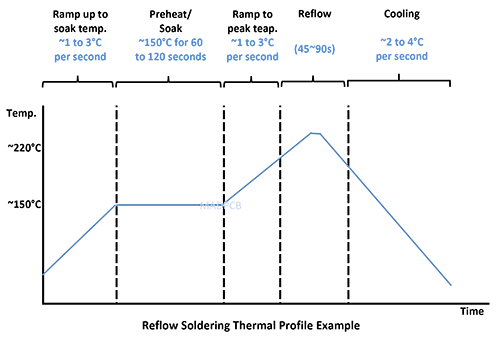
On a double-track conveyor belt, the PCB boards with newly-placed components are passed through hot and cool zones of the reflow furnace. These steps are meant to precisely control the melting and cooling of the solder to fill in the solder points. The main temperature changes associated with the reflow soldering temperature curve can be divided into four phases/zones, including Preheat, Thermal Soak, Reflow and Cooling.
Correctly profiling the temperature of the reflow tunnel or chamber ensures that the resulting soldering joints are of the highest quality at best yield. The four stages normally used as follows:
- Preheat: The boards need to be brought steadily up to the required temperature. If the rate is too high, then the board or the components may be damaged by the thermal stress. Additionally, if the printed circuit board is brought up to temperature too quickly then areas may not reach the required temperature because of the thermal mass. If the board is brought to temperature too slowly, then the board may not reach the required temperature. The temperature rise rate is often used for infra-red soldering is between 2 and 3°C pre second, although rise rates down to 1°C per second may be used on some occasions.
- Thermal Soak: Having brought the board up to temperature it next enters what is often termed a thermal soak area. Here the card is maintained at temperature for two reasons. One is to ensure that any areas that are not adequately heated because shadowing effects come up to the required temperature. The other is to remove the solder paste solvents or volatiles and to activate the flux.
- Reflow: The reflow area is the area of the soldering process where the highest temperature is reached. It is here that the solder is caused to melt and create the required solder joints. The actual reflow process involves the flux reducing the surface tension at the junction of the metals to accomplish metallurgical bonding, allowing the individual solder powder spheres to combine and melt.
- Cooling: The cooling for the boards after reflow must be accomplished in a way that does not cause stress to the components. Proper cooling inhibits excess intermetallic formation or thermal shock to the components. Typical temperatures in the cooling zone range from 30-100° The temperature in this zone creates a relatively fast cooling rate and this is chosen to create a fine grain structure in the solder to provide the most mechanically sound solder joints.

