Table of Contents
Rigid PCB Profiling: V-Scoring | V-Cut
PCB V-Scoring, also referred to V-Grooving, or V-Cut, which is a process of cutting a “V” shaped groove at the top and bottom of a rigid board and leaving a thin thickness between the both Vees. V-scoring process has been used for many years in the production of printed circuit boards (PCBs) with rigid materials, including FR4, metal core, PTFE and CEM materials. V-soring is not applicable for flexible circuits.
Why Use V-Scoring?
In PCB manufacturing, v-scoring is used primarily when panelizing a set of PCB boards together in a panel to make the PCB assembly more efficient. The idea behind v-scoring the boards is to provide a solid support structure for the assembly process that would allow for minimal pressure to be applied to the boards when the SMT machines place SMD components onto the PCB boards, then separate the assembled boards (PCBAs). A PCB panel makes PCB assembly manufacturers to load components (/parts) at a much faster rate because they can do the panel at one time instead of loading one board at a time. The boards on panel are loaded with parts using automated pick-and-place machine. That are why PCB manufacturers, PCB buyers and assembly manufacturer are willing to use V-scoring panelization.
Terms of V-scoring Panel:
- Rails: also referred to waste tabs or border. Rails are not the parts of the PCB board, but the extra material around your PCB(s) to form a panel. Rail is usually applied for enforce the mechanical stability of the panel and allows non-functional material outside the PCB which can be used for clamping the panel during assembly.
- Fiducials: Fiducials are little target registration marks that etched on panel rails or inside of PCBs on top and/or bottom copper layers, and allow the vision system of the SMT machines to recognize where the PCB is at, and where the SMD components are placed.
- Tooling Holes: Tooling holes in the four corners of the PCB panel rails be used by the PCB fabricators for aligning the board during drilling, routing and E-test fixtures; the assemblers for alignment with stencils during solder pate printing, and for alignment with SMT carriers, PCBA testing fixtures, or final enclosure assembly (mating with small moulded plastic posts).
What’s V-Scoring Process?
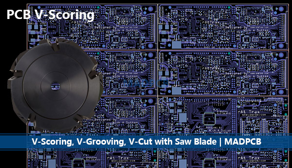
The V-scoring process consists of two blades with any angle, like 30o, 45o and 60o beveling. The blade likes a wheel with many gears, and the gears are the knives to score. One blade is on top and the other is on bottom, they are rotating and point-to-point with a certain distance required to let the PCB boards pass through. The distance determines the remaining thickness in the middle of the two Vees. The remaining thickness supports PCB units held together the sub-panels (/set) or the production panels. After PCB board assembly process, the sub-panels will be divided into individual PCB assembly.
V-Scoring Rules
A common misunderstanding is that the perfect PCB size is one which would fit exactly within an 18’’ x 24’’ CCL sheet. In reality, the PCB fabricator must sacrifice some of the available sheet area for processing. For PCB panel, just be sure to work with your PCB manufacturer to determine the best PCB panel for your next project. Your PCB manufacturer should be able to assist with PCB panelization. While, sometimes customer would like to provide their own PCB panels.
In this circumstance, just follow the following V-scoring rules:
- Board-to-Board space is 0mm.
- Min PCB size for V-scoring is 75x75mm, max PCB size is 450x1250mm.
- V-scoring line must be straight, can be continuous or dis-continuous. (Dis-continuous v-scoring called as Jump V-scoring).
- Min PCB thickness for V-scoring is 0.6mm.
- V-scoring angles can be 30o, 45o and 60o.
- Min 6.35mm (250mil) space between edge of the board and parts need to placed.

