What are Electrical Waveforms?
Technically speaking, Electrical Waveforms are basically visual representations of the variation of a voltage or current over time. This means that if we plotted these voltage or current variations on a piece of graph paper against a base (x-axis) of time (t) the resulting plot or drawing would represent the shape of a Waveform as shown. There are many different types of electrical waveforms available but generally they can all be broken down into two distinctive groups.
- Uni-directional Waveforms: these electrical waveforms are always positive or negative in nature flowing in one forward direction only as they do not cross the zero-axis point. Common uni-directional waveforms include Square-wave timing signals, Clock pulses and Trigger pulses.
- Bi-directional Waveforms: these electrical waveforms are also called alternating waveforms as they alternate from a positive direction to a negative direction constantly crossing the zero-axis point. Bi-directional waveforms go through periodic changes in amplitude, with the most common by far being the Sine-wave.
Whether the waveform is uni-directional, bi-directional, periodic, non-periodic, symmetrical, non-symmetrical, simple or complex, all electrical waveforms include the following three common characteristics:
- Period: This is the length of time in seconds that the waveform takes to repeat itself from start to finish. This value can also be called the Periodic Time (T) of the waveform for sine waves, or the Pulse Width for square waves.
- Frequency: This is the number of times the waveform repeats itself within a one second time period. Frequency is the reciprocal of the time period (ƒ = 1/T) with the standard unit of frequency being the Hertz (Hz).
- Amplitude: This is the magnitude or intensity of the signal waveform measured in volts or amps.
Periodic Waveforms
Periodic waveforms are the most common of all the electrical waveforms as it includes Sine Waves. The AC (Alternating Current) mains waveform in your home is a sine wave and one which constantly alternates between a maximum value and a minimum value over time.
The amount of time it takes between each individual repetition or cycle of a sinusoidal waveform is known as its “periodic time” or simply the Period of the waveform. In other words, the time it takes for the waveform to repeat itself.
Then this period can vary with each waveform from fractions of a second to thousands of seconds as it depends upon the frequency of the waveform. For example, a sinusoidal waveform which takes one second to complete its cycle will have a periodic time of one second. Likewise, a sine wave which takes five seconds to complete will have a periodic time of five seconds and so on.
So, if the length of time it takes for the waveform to complete one full pattern or cycle before it repeats itself is known as the “period of the wave” and is measured in seconds, we can then express the waveform as a period number per second denoted by the letter T as shown below.
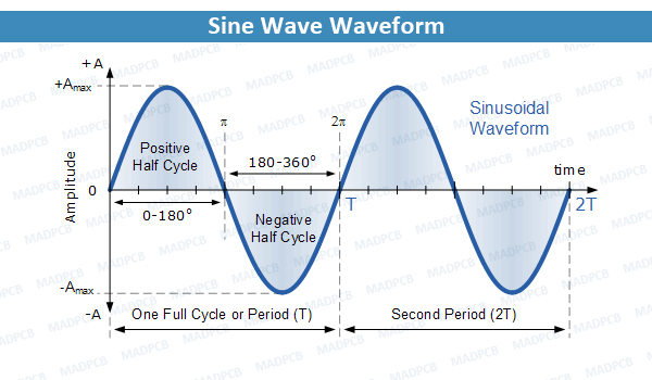
Sine Wave Waveform
Units of periodic time (T): Seconds (s), milliseconds (ms) and microseconds (μs).
For sine wave waveforms only, we can also express the periodic time of the waveform in either degrees or radians, as one full cycle is equal to 360o (T = 360o) or in Radians as 2pi, 2π (T = 2π), then we can say that 2π radians = 360o.
We now know that the time it takes for electrical waveforms to repeat themselves is known as the periodic time or period which represents a fixed amount of time. If we take the reciprocal of the period (1/T) we end up with a value that denotes the number of times a period or cycle repeats itself in one second or cycles per second, and this is commonly known as Frequency with units of Hertz, (Hz). Then Hertz can also be defined as “cycles per second” (cps) and 1Hz is exactly equal to 1 cycle per second.
Both period and frequency are mathematical reciprocals of each other and as the periodic time of the waveform decreases, its frequency increases and vice versa with the relationship between Periodic time and Frequency given as.
Relationship between Frequency and Periodic Time
Frequency = 1 / Periodic Time, or f = 1 / T (Hz)
Periodic Time = 1 / Frequency, or T = 1 / f (sec)
One Hertz is exactly equal to one cycle per second, but one hertz is a very small unit, so prefixes are used that denote the order of magnitude of the waveform such as kHz, MHz and even GHz.
|
Prefix |
Definition | Written as | Time Period |
| Kilo | Thousand | kHz |
1ms |
|
Mega |
Million | MHz | 1us |
| Giga | Billion | GHz |
1ns |
|
Tera |
Trillion | THz |
1ps |
Square Wave Electrical Waveforms
Square-wave Waveforms are used extensively in electronic and microelectronic circuits for clock and timing control signals as they are symmetrical waveforms of equal and square duration representing each half of a cycle and nearly all digital logic circuits use square wave waveforms on their input and output gates.
Unlike sine waves which have a smooth rise and fall waveform with rounded corners at their positive and negative peaks, square waves on the other hand have very steep almost vertical up and down sides with a flat top and bottom producing a waveform which matches its description, – “Square” as shown below.
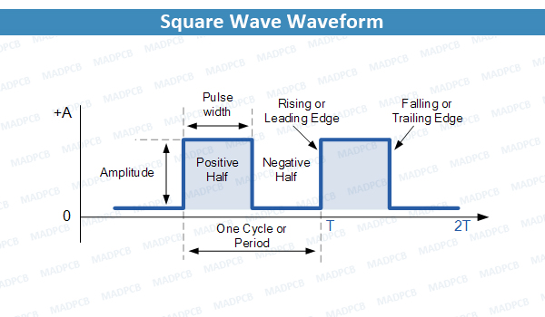
Square Wave Waveform
We know that square shaped electrical waveforms are symmetrical in shape as each half of the cycle is identical, so the time that the pulse width is positive must be equal to the time that the pulse width is negative or zero. When square wave waveforms are used as “clock” signals in digital circuits the time of the positive pulse width is known as the “Duty Cycle” of the period.
Then we can say that for a square wave waveform the positive or “ON” time is equal to the negative or “OFF” time so the duty cycle must be 50%, (half of its period). As frequency is equal to the reciprocal of the period (1/T) we can define the frequency of a square wave waveform as:
Frequency = 1 / (“ON” Time + “OFF” Time)
Electrical Waveforms Example 1: A Square Wave electrical waveform has a pulse width of 10ms, calculate its frequency (ƒ). For a square wave shaped waveform, the duty cycle is given as 50%, therefore the period of the waveform must be equal to: 10ms + 10ms or 20ms, then
Frequency = 1 / Period = 1 / (10mS + 10mS) = 50Hz
A Square Wave Waveform is symmetrical in shape and has a positive pulse width equal to its negative pulse width resulting in a 50% duty cycle. Square wave waveforms are used in digital systems to represent a logic level “1”, high amplitude and logic level “0”, low amplitude. If the duty cycle of the waveform is any other value than 50%, (half-ON half-OFF) the resulting waveform would then be called a Rectangular Waveform or if the “ON” time is really small a Pulse.
Rectangular Waveforms
Rectangular Waveforms are similar to the square wave waveform above, the difference being that the two pulse widths of the waveform are of an unequal time period. Rectangular waveforms are therefore classed as “Non-symmetrical” waveforms as shown below.
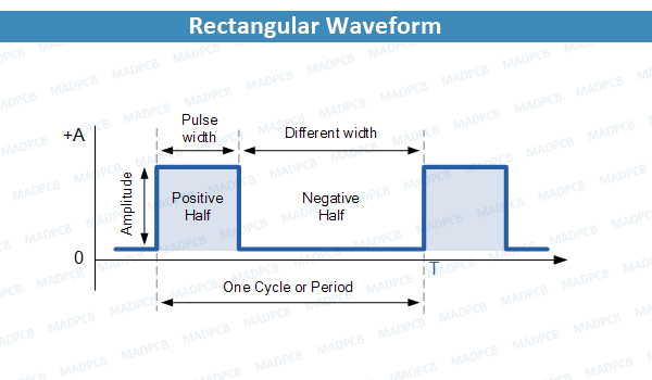
Rectangular Waveform
The example above shows that the positive pulse width is shorter in time than the negative pulse width. Equally, the negative pulse width could be shorter than the positive pulse width, either way the resulting waveform shape would still be that of a rectangular waveform.
These positive and negative pulse widths are sometimes called “Mark” and “Space” respectively, with the ratio of the Mark time to the Space time being known as the “Mark-to-Space” ratio of the period and for a Square wave waveform this would be equal to one.
Electrical Waveforms Example 2: A Rectangular waveform has a positive pulse width (Mark time) of 10ms and a duty cycle of 25%, calculate its frequency. The duty cycle is given as 25% or 1/4 of the total waveform which is equal to a positive pulse width of 10ms. If 25% is equal to 10mS, then 100% must be equal to 40mS, so then the period of the waveform must be equal to: 10ms (25%) + 30ms (75%) which equals 40ms (100%) in total, then
Frequency = 1 / Period = 1 / (10mS + 30mS) = 25Hz
Rectangular Waveforms can be used to regulate the amount of power being applied to a load such as a lamp or motor by varying the duty cycle of the waveform. The higher the duty cycle, the greater the average amount of power being applied to the load and the lower the duty cycle, the less the average amount of power being applied to the load and an excellent example of this is in the use of “Pulse Width Modulation” speed controllers.
Triangular Waveforms
Triangular Waveforms are generally bi-directional non-sinusoidal waveforms that oscillate between a positive and a negative peak value. Although called a triangular waveform, the triangular wave is actually more of a symmetrical linear ramp waveform because it is simply a slow rising and falling voltage signal at a constant frequency or rate. The rate at which the voltage changes between each ramp direction is equal during both halves of the cycle as shown below.
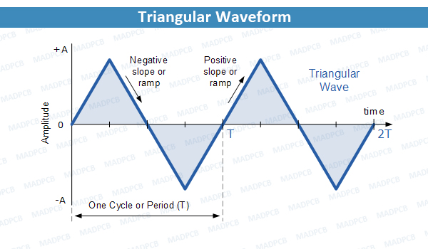
Triangular Waveform
Generally, for Triangular Waveforms the positive-going ramp or slope (rise), is of the same time duration as the negative-going ramp (decay) giving the triangular waveform a 50% duty cycle. Then any given voltage amplitude, the frequency of the waveform will determine the average voltage level of the wave.
So, for a slow rise and slow delay time of the ramp will give a lower average voltage level than a faster rise and decay time. However, we can produce non-symmetrical triangular waveforms by varying either the rising or decaying ramp values to give us another type of waveform known commonly as a Sawtooth Waveform.
Sawtooth Waveforms
Sawtooth Waveforms are another type of periodic waveform. As its name suggests, the shape of the waveform resembles the teeth of a saw blade. Sawtooth waveforms can have a mirror image of themselves, by having either a slow-rising but extremely steep decay, or an extremely steep almost vertical rise and a slow-decay as shown below.
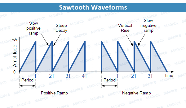
Sawtooth Waveforms
The positive ramp Sawtooth Waveform is the more common of the two waveform types with the ramp portion of the wave being almost perfectly linear. The Sawtooth waveform is commonly available from most function generators and consists of a fundamental frequency (ƒ) and all its integer ratios of harmonics, such as: 1/2, 1/4, 1/6 1/8 … 1/n etc. What this means in practical terms is that the Sawtooth Waveform is rich in harmonics and for music synthesizers and musicians gives the quality of the sound or tonal color to their music without any distortion.
Triggers and Pulses
Although technically Triggers and Pulses are two separate waveforms, we can combine them together here, as a “Trigger” is basically just a very narrow “Pulse”. The difference being is that a trigger can be either positive or negative in direction whereas a pulse is only positive in direction.
A Pulse Waveform or “Pulse-train” as they are more commonly called, is a type of non-sinusoidal waveform that is similar to the Rectangular waveform we looked at earlier. The difference being that the exact shape of the pulse is determined by the “Mark-to-Space” ratio of the period and for a pulse or trigger waveform the Mark portion of the wave is very short with a rapid rise and decay shape as shown below.
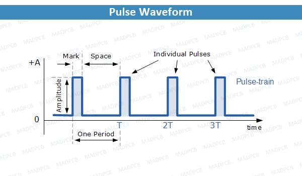
Pulse Waveform
A Pulse is a waveform or signal in its own right. It has very different Mark-to-Space ratio compared to a high frequency square wave clock signal or even a rectangular waveform.
The purpose of a “Pulse” and that of a trigger is to produce a very short signal to control the time at which something happens for example, to start a Timer, Counter, Monostable or Flip-flop etc, or as a trigger to switch “ON” Thyristors, Triacs and other power semiconductor devices.
Function Generator
A Function Generator or sometimes called a Waveform Generator is a device or circuit that produces a variety of different waveforms at a desired frequency. It can generate Sine waves, Square waves, Triangular and Sawtooth waveforms as well as other types of output waveforms.
Many “off-the-shelf” waveform generator ICs are available, and all can be incorporated into a circuit to produce the different periodic waveforms required.
One such device is a precision waveform generator IC capable of producing sine, square and triangular output waveforms, with a minimum number of external components or adjustments. Its operating frequency range can be selected over eight decades of frequency, from 0.001Hz to 300kHz, by the correct choice of the external R-C components.

Waveform Generator IC
The frequency of oscillation is highly stable over a wide range of temperature and supply voltage changes and frequencies as high as 1MHz is possible. Each of the three basic waveform outputs, sinusoidal, triangular and square are simultaneously available from independent output terminals. The frequency range is voltage controllable but not a linear function. The triangle symmetry and hence the sine wave distortion are adjustable.