What Is A Parallel Circuit?
A Parallel Circuit comprises branches so that the current divided and only part of it flows through any branch. The voltage, or potential difference, across each branch of a parallel circuit is the same, but the currents may vary.
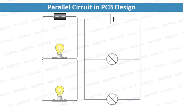
Parallel Circuit in PCB Design
If two or more components are connected in parallel, they have the same difference of potential (voltage) across their ends. The potential differences across the components are the same in magnitude, and they also have identical polarities. The same voltage is applied to all circuit components connected in parallel. The total current is the sum of the currents through the individual components, in accordance with Kirchhoff’s current law.
When it comes to diagram capture in PCB design, do you know the circuits with parallel capacitors, resistors and inductors? Read to know more about these simple parallel circuits.
Also see the term Series Circuit
Voltage
In a parallel circuit, the voltage is the same for all elements.
V = V1 = V2 = … = Vn
Current
The current in each individual resistor is found by Ohm’s law. Factoring out the voltage gives
Itotal = I1 + I2 + … + In = V (1/R1 + 1/R2 + … + 1/Rn)
Resistance Units
To find the total resistance of all components, add the reciprocals of the resistances Ri of each component and take the reciprocal of the sum. Total resistance will always be less than the value of the smallest resistance:
1/Rtotal = 1/R1 + 1/R2 + … + 1/Rn
For only two resistances, the unreciprocated expression is reasonably simple:
Rtotal = R1R2/(R1+R2)
This sometimes goes by the mnemonic product over sum.
For N equal resistances in parallel, the reciprocal sum expression simplifies to:
1/Rtotal = N*1/R
And therefore to:
Rtotal = R/N
To find the current in a component with resistance Ri, use Ohm’s law again:
Ii = V/Ri
The components divide the current according to their reciprocal resistances, so, in the case of two resistors,
I1/I2 = R2/R1
The components divide the current according to their reciprocal resistances, so, in the case of two resistors,
Since electrical conductance G is reciprocal to resistance, the expression for total conductance of a parallel circuit of resistors reads:
Gtotal = G1 + G2 + … + Gn
The relations for total conductance and resistance stand in a complementary relationship: the expression for a series connection of resistances is the same as for parallel connection of conductances, and vice versa.
Inductors
Inductors follow the same law, in that the total inductance of non-coupled inductors in parallel is equal to the reciprocal of the sum of the reciprocals of their individual inductances:
1/Ltotal = 1/L1 + 1/L2 + … + 1/Ln
If the inductors are situated in each other’s magnetic fields, this approach is invalid due to mutual inductance. If the mutual inductance between two coils in parallel is M, the equivalent inductor is:
1/Ltotal = (L1 + L2 – 2M)/(L1L2 – M2)
If L1 = L2
Ltotal = (L+M)/2
The sign of M depends on how the magnetic fields influence each other. For two equal tightly coupled coils the total inductance is close to that of every single coil. If the polarity of one coil is reversed so that M is negative, then the parallel inductance is nearly zero or the combination is almost non-inductive. It is assumed in the “tightly coupled” case M is very nearly equal to L. However, if the inductances are not equal and the coils are tightly coupled there can be near short circuit conditions and high circulating currents for both positive and negative values of M, which can cause problems.
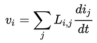
More than three inductors become more complex and the mutual inductance of each inductor on each other inductor and their influence on each other must be considered. For three coils, there are three mutual inductances M12, M13 and M23. This is best handled by matrix methods and summing the terms of the inverse of the L matrix (3 by 3 in this case).
The pertinent equations are of the form:
Equation
Capacitors
The total capacitance of capacitors in parallel is equal to the sum of their individual capacitances:
Ctotal = C1 + C2 + … + Cn
The working voltage of a parallel combination of capacitors is always limited by the smallest working voltage of an individual capacitor.
Switches
Two or more switches in parallel form a logical OR; the circuit carries current if at least one switch is closed. See OR gate.
Cells and Batteries
If the cells of a battery are connected in parallel, the battery voltage will be the same as the cell voltage, but the current supplied by each cell will be a fraction of the total current. For example, if a battery comprises four identical cells connected in parallel and delivers a current of 1 ampere, the current supplied by each cell will be 0.25 ampere. If the cells are not identical, cells with higher voltages will attempt to charge those with lower ones, potentially damaging them.
Parallel-connected batteries were widely used to power the valve filaments in portable radios. Lithium-ion rechargeable batteries (particularly laptop batteries) are often connected in parallel to increase the ampere-hour rating. Some solar electric systems have batteries in parallel to increase the storage capacity; a close approximation of total amp-hours is the sum of all amp-hours of in-parallel batteries.
MADPCB is a one-top PCB provider with services, including PCB manufacturing, SMT assembly, PCB layout, parts sourcing, IC programming and functional testing. Contact us now to get quick quote from our professional sales engineers.