What Is A Series Circuit?
A Series Circuit is a path for transmitting electric current, and which comprises a path along which the whole current flows through each component.
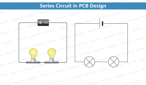
Series Circuit in PCB Design
Series circuits are sometimes referred to as current-coupled or daisy chain-coupled. The electric current in series circuit goes through every component in the circuit. Therefore, all of the components in a series connection carry the same current.
A series circuit has only one path in which its current can flow. Opening or breaking a series circuit at any point causes the entire circuit to “open” or stop operating. For example, if even one of the light bulbs in an older-style string of Christmas tree lights burns out or is removed, the entire string becomes inoperable until the bulb is replaced.
In printed circuit board (PCB) design, when it comes to diagram capture, you always meet series circuits, like series resistor, series inductor, and series capacitor. What’s their function and basic law? Scroll down for knowing more.
Also see the term Parallel Circuit
Current
I = I1 = I2 = … = In
In a series circuit, the current is the same for all of the elements.
Voltage
In a series circuit, the voltage is the sum of the voltage drops of the individual components (resistance units).
V = V1 + V2 + … + Vn = I(R1 + R2 + … + Rn)
Resistance Units
The total resistance of two or more resistors connected in series is equal to the sum of their individual resistances:
Rtotal = Rs = R1 + R2 + … + Rn
Here, the subscript s in Rs denotes “series”, and Rs denotes resistance in a series.
Electrical conductance presents a reciprocal quantity to resistance. Total conductance of a series circuits of pure resistance, therefore, can be calculated from the following expression:
1/Gtotal = 1/G1 + 2/G2 + … + 1/Gn
For a special case of two conductances in series, the total conductance is equal to:
Gtotal = G1G2 / (G1 + G2)
Inductors
Inductors follow the same law, in that the total inductance of non-coupled inductors in series is equal to the sum of their individual inductances:
However, in some situations, it is difficult to prevent adjacent inductors from influencing each other as the magnetic field of one device couples with the windings of its neighbors. This influence is defined by the mutual inductance M. For example, if two inductors are in series, there are two possible equivalent inductances depending on how the magnetic fields of both inductors influence each other.
When there are more than two inductors, the mutual inductance between each of them and the way the coils influence each other complication. For a larger number of coils the total combined inductance is given by sum of all mutual inductances between the various coils, including the mutual inductance of each given coil itself, which we term self-inductance or simply inductance. For three coils, there are six mutual inductances M12, M13, M23 and M21, M31 and M32. There are also the three self-inductances of the three coils: M11, M22 and M33.
Therefore
Ltotal = (M11 + M22 + M33) + (M12 + M13 + M23) + (M21 + M31 + M32)
By reciprocity, Mij = Mji so that the last two groups can be combined. The first three terms represent the sum of the self-inductances of the various coils. The formula is easily extended to any number of series coils with mutual coupling. The method can be used to find the self-inductance of large coils of wire of any cross-sectional shape by computing the sum of the mutual inductance of each turn of wire in the coil with every other turn since in such a coil all turns are in series.
Capacitors
Capacitors follow the same law using the reciprocals. The total capacitance of capacitors in series is equal to the reciprocal of the sum of the reciprocals of their individual capacitances:
1 / CTotal = 1/C1 + 1/C2 + … + 1/Cn
Cells and Batteries
A battery is collection of electrochemical cells. If the cells are connected in series, the voltage of the battery will be the sum of the cell voltages. For example, a 12 volt car battery contains six 2-volt cells connected in series. Some vehicles, such as trucks, have two 12 volt batteries in series to feed the 24-volt system.
MADPCB is a one-top PCB provider with services, including PCB manufacturing, SMT assembly, PCB layout, parts sourcing, IC programming and functional testing. Contact us now to get quick quote from our professional sales engineers.