What is Power Dissipation?
Power Dissipation is the process by which an electronic or electrical device produces heat (energy loss or waste) as an undesirable derivative of its primary action. You can understand that the amount of heat energy generated by a device in one second when current flows through it.
Power Dissipation
Power dissipation in resistors is considered a naturally occupying phenomenon. The fact remains that all resistors that are part of a circuit and has a voltage drop across it will dissipate electrical power. Moreover, this electrical power converts into heat energy, and therefore all resistors have a (power) rating. Also, a resistor’s power rating is a classification that parameterizes the maximum power that it can dissipate before it reaches critical failure.
The unit Watt (W) is how we express power, and the formula for power is P (power) = I (current) x E (voltage). In regards to the laws of physics, if there is an increase in voltage (E), then the current (I) will also increase, and the power dissipation of a resistor, will, in turn, increase as well. However, if you increase the value of the resistor, current will decrease, and the resistor’s power dissipation will decrease as well. The correction follows Ohm’s Law, which states the formula for current as I (current) = V (voltage) / R (resistance).
How to Calculate the Power Dissipation by a Resistor?
In the field of electronics, power dissipation is also a measurement parameter that quantifies the releasing of heat within a circuit due to inefficiencies. In other words, power dissipation is a measure of how much power (P = I x E) in a circuit is converted into heat. As I mentioned earlier, each resistor has a power rating, and in terms of PCB design, this allows designers to assess whether or not a particular resistor will meet their design needs within a circuit. So, now, let’s take a closer look at how to calculate this critical design parameter.
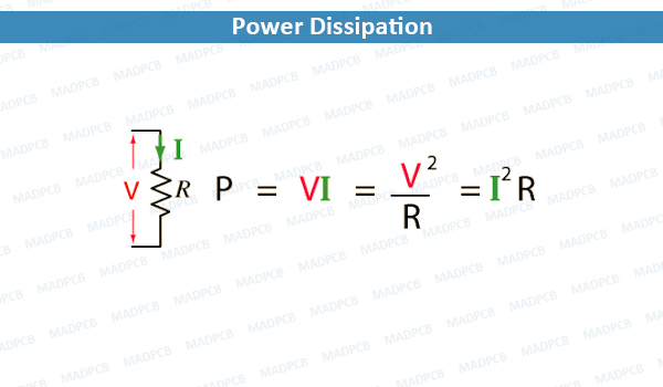
Firstly, according to Ohm’s law,
V (voltage) = I (current) × R (resistance)
I (current) = V (voltage) ÷ R (resistance)
P (power) = I (current) × V (voltage)
Therefore, to calculate the power dissipated by the resistor, the formulas are as follows:
P (power dissipated) = I2 (current) × R (resistance)
or
P (power dissipated) = V2 (voltage) / R (resistance)
So, using the above circuit diagram as our reference, we can apply these formulas to determine the power dissipated by the resistor.
Voltage = 9V
Resistance = 100Ω
I (current) = 9V / 100Ω or I (current) = 90 mA
P (power) = 90 mA × 9V or P (power) = 0.81 W or 810 mW
P (power dissipated) = V2 (voltage) ÷ R (resistance)
or
P (power dissipated) = 92 ÷ 100
or
P (power dissipated) = 81 /100 or P (power dissipated) = 810 mW
Power Dissipation: Good or Bad?
Generally speaking, no; however, there are some instances where heat dissipation is a good thing. Take, for example, electric heaters that use resistance wire such as Nichrome. Nichrome is a unique heating element due to its cost-effectiveness, resistance to the flow of electrons, strength, flexibility, resistance to oxidation, and stability in high temperatures.
Also, another instance where heat dissipation is favorable is with incandescent light bulbs, which are in use as cost-effective heaters. Overall, under normal circumstances, heat dissipation is not desirable, but on the rare occasions that it is, it will then consist of efforts to control the heat dissipation rather than moderate it.
Now here are some essential points of emphasis when approaching power dissipation.
- Ensure your resistor’s power rating meets your circuit design needs.
- Be sure to double-check whether your IC’s rating is contingent on the use of heatsinks.
- If you are designing PCBs, ensure your traces are large enough to keep resistance low and avoid excessive heating.
- When designing a switching circuit, be sure to keep your switching time short as much as possible.
To reduce switching times, make the slew rate as steep as possible, by reducing the capacitance on the line. Also, in the field of electronics, a slew rate is defined as the change of current, voltage, or other electrical measures, within a unit of time.
As printed circuit board (PCB) designers, you continuously face the ever-present challenge in electronic circuit design. One of the most critical aspects of design is finding the correct components that meet your circuit needs. Furthermore, finding these components also means that they must safely function within the given parameters of voltage, power, and current. Therefore, calculating parameters like power dissipation is critical to your overall circuit design.