What’s Reference Designator in PCB?
Reference Designator (abbreviation “Ref Des” or “REFDES“) is the name of component on a printed circuit by convention beginning with one or more letters followed by a numeric value. The letter designates the class of component; eg. “Q” is commonly used as a prefix for transistors. Reference designators appear as usually white silkscreen epoxy ink printed on a circuit board. They are placed close to their respective components but not underneath them, so that they are visible on the assembled board. By contrast, on an assembly drawing, a reference designator is often placed within the boundaries of a footprint — a very useful technique for eliminating ambiguity on a crowded board where reference designators in the silkscreen may be near more than one component.
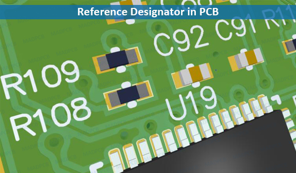
Reference Designator in PCB
Reference designators are unique identifying labels for each physical component and they communicate a lot about the components to which they refer. Proper REFDES use tells the schematic reader the type of component and the number of symbols per component. While there are standard symbols that represent various types of electrical components, which we will discuss next, not all schematics follow all of those standards.
In a case where every passive component is shown as a generic box with pins, reference designator prefixes can tell you a lot about the type of component that symbol represents. Reference designators also serve as the link to the bill of materials (BOM). The BOM has the part number of every component in your PCB assembly design, and it indicates which locations should have that part installed, by REFDES.
How to Make Reference Designators on PCB?
In PCB manufacturing, the reference designators can be
- silk screened on overlay (/silkscreen) layers (GTO, GBO)
- etched on outer copper layers (GTL, GBL) with solder mask openings
- ablated by laser directly on solder mask layers (GTS, GBS).
Reference Designator Industry-standard Format
The industry-standard format for reference designators includes a letter code, indicating the type of component, followed by a unique number.
- BT = Battery
- C = Capacitor
- D = Diode
- F = Fuse
- H = Hardware
- J = Connector
- K = Relay
- L = Inductor
- P = Connector
- Q = Transistor
- R = Resistor
- S or W = Switch
- T = Transformer
- U = Integrated Circuit
- Y = Crystal