What is a Regulated Power Supply?
A Regulated Power Supply is an embedded circuit, which converts unregulated AC into a constant DC. With the help of a rectifier, it converts AC supply into DC. Its function is to supply a stable voltage to a circuit or device that must be operated within certain power supply limits. The output from the regulated power supply may be alternating or unidirectional, but is nearly always DC. The type of stabilization used may be restricted to ensuring that the output remains within certain limits under various load conditions, or it may also include compensation for variations in its own supply source. The latter is much more common today.
Without voltage, any electronics will not function. A power supply is a vital component that supplies the voltage and allows current to flow through. This activates components like IC (integrated chips), MCU (microcontrollers), and allows passive components to behave accordingly.
A power supply can be regulated or unregulated. An unregulated power supply is not guaranteed to maintain a specific voltage level during operation. This means that if you’re using a 5V unregulated power supply, there could be a fluctuation on the voltage and components powered may be affected.
On the other hand, this power supply ensures that the output to the load is stable and at a level that it is rated to function. A regulated power supply is crucial in ensuring the proper functioning of electronics components. It enables components to be powered with a consistent voltage value, with the condition that the load current is within the power supply’s limit.
Linear vs. Switching?
In most PCB designs, you’ll be required to include a regulated power supply module on the product. In fact, the power supply is the top priority of any designers before they started planning on other parts of the circuit. That’s because, without a reliable regulated power supply, the product will be unstable.
When it comes to a regulated power supply, PCB designers are often torn between linear and switching regulated power supply. Both will produce the stable voltage required by the components. The linear regulated power supply is cheaper, but is inefficient and dissipates more heat.
Meanwhile, the switching one is more expensive and requires more passive components to be connected. However, it is more efficient and doesn’t heat up easily.
The decision on opting for a linear or switching regulated power supply depends on a few factors. While the linear power supply is attractively economical, its inefficiency makes it a poor choice for circuits that demand higher power. However, simple circuits with minimal components can benefit from the linear regulated power supply design.
5 Tips for PCB Design
In PCB design, such power supply often involves a voltage regulator. While the voltage regulator could function even if some of the best practices are not adhered to, but it may not perform as well when pushed to the limit.
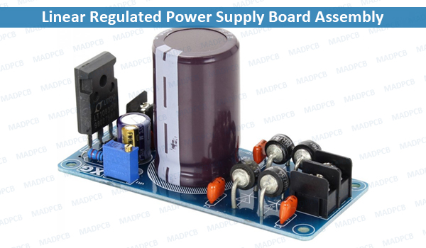
Linear Regulated Power Supply Board Assembly
- Power Budget Calculation: Before you choose a voltage regulator for the design, you’ll want to run through every active and passive component to calculate the maximum power they will consume. This is crucial as it will ultimately affect the decision of voltage regulator selection. In other words, you wouldn’t want to end up with some pants that doesn’t fit.
- Choosing the Right Voltage Regulator: Once you’ve ascertained the peak current consumption by the circuit, you’ll want to choose a voltage regulator that is able to support that. However, the voltage regulator is always to allow some margin so that any changes in the circuit will not affect the chosen voltage regulator. For example, if the load is estimated to consume 1.5A, having a 2A voltage regulator allows some safety barrier.
- Bypass Capacitors: they help to stabilize the output of the voltage regulator. You’ll need one when using a linear voltage regulator and even more so when using a switching regulator. That’s because switching regulator alternates between on and off state to transfer the voltage at the input to the output. Often, this can introduce ripple to the output.
- Low Impedance: To increase the efficiency of the regulated power supply design, you’ll want to ensure the voltage regulator and its associated components are connected with low impedance trace. This means having the components close to the voltage regulator and using vias to minimize impedance between layers.
- Heat Dissipation: When driving a substantial load, even switching voltage regulator will heat up. The temperature rise can be calculated from the temperature coefficient in the datasheet. In your design, you’ll want to mitigate heat dissipation. This can be in the form of a physical heat sink or turn your PCB into one. Using thermal vias can reduce the heat from building up in areas close to the voltage regulator.
Keep in mind, if you are considering only DC to DC conversion, then grounding as a plane is fine. But if you want to discuss AC to DC conversion, then grounding should be given high importance. There must be good separation between analog and digital ground, and jumpers must be provided in PCB design to connect grounds when required.