What Is a Relay?
A Relay is an electromagnetic switch operated by a relatively small electric current that can turn on or off a much larger electric current. The heart of a relay is an electromagnet (a coil of wire that becomes a temporary magnet when electricity flows through it). It consists of a set of input terminals for a single or multiple control signals, and a set of operating contact terminals. The switch may have any number of contacts in multiple contact forms, such as make contacts, break contacts, or combinations thereof.
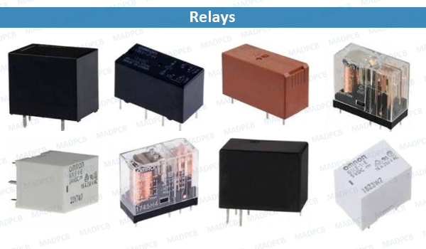
PCB Power Relays
Relays are used where it is necessary to control a circuit by an independent low-power signal, or where several circuits must be controlled by one signal. Relays were first used in long-distance telegraph circuits as signal repeaters: they refresh the signal coming in from one circuit by transmitting it on another circuit. Relays were used extensively in telephone exchanges and early computers to perform logical operations.
The traditional form of a relay uses an electromagnet to close or open the contacts, but other operating principles have been invented, such as in solid-state relays which use semiconductor properties for control without relying on moving parts. Relays with calibrated operating characteristics and sometimes multiple operating coils are used to protect electrical circuits from overload or faults; in modern electric power systems these functions are performed by digital instruments still called protective relays.
Latching relays require only a single pulse of control power to operate the switch persistently. Another pulse applied to a second set of control terminals, or a pulse with opposite polarity, resets the switch, while repeated pulses of the same kind have no effects. Magnetic latching relays are useful in applications when interrupted power should not affect the circuits that the relay is controlling.
Basics of Circuit Relays
Relays range from electromagnetic and reed relays to solid-state, hybrid, and thermal relays. A standard AC or DC electromagnetic relay consists of an electromagnet that receives an electric signal and converts the signal into the mechanical action of a switch that opens and closes the circuit. A reed relay features a pair of magnetic strips (the reed) sealed within a glass tube. Applying a magnetic field to the coil causes the reeds to act as an actuator and a contact blade while switching occurs.
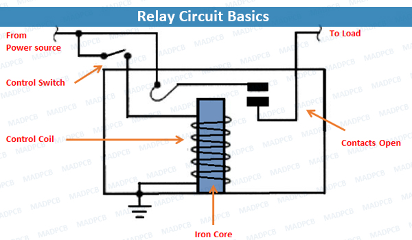
Relay Circuit Basics
Any increase in ambient temperature from the limit causes the contacts of a thermal relay to switch from one position to another as it protects a motor or other device from an overload condition. In contrast to electromagnetic, reed, and thermal relays, solid state relays have no moving parts. The different types of solid state relays include reed relay-coupled relays, transformer coupled relays, and photo-coupled relays. Hybrid relays combine electromagnetic relays with electronic components.
Applications for relays include consumer electronic devices, industrial machinery, control panels, medical and scientific equipment, communications equipment, and transportation. Consumer devices ranging from cellular phones to ovens and stoves include relays as part of control circuitry. In the automotive industry, relays control doors, automatic breaking systems, the power steering, power windows, and sunroofs. Conveyor belts, elevators, and lifts also rely on relays.
We can classify relays by contacts, mounting type, construction, or function. Depending on the application, relays may either utilize contacts or may not have any contacts. As an example, contact forms for electromagnetic relays include the single-pole single throw, double-pole single throw, and double-pole double throw relays.
Specific types of boards may require discrete mounting relays or surface mount relays. In terms of construction, some applications may use sealed relays while others require flux protection relays. Single-side relays turn on or turn off after receiving an input signal. In contrast, latching relays remain on or off after receiving an input signal.
Electromechanical and Reed Relays
Electromechanical and reed relays used for switch resistive and inductive loads for the power management of control systems. The relays mount directly to a PCB and fit a compact standard relay package. An electromechanical PCB relay includes a coil, an armature, and contacts. Applying power to the coil forms a magnetic field that causes the armature to move and the contacts to open or close. Electromechanical relays have excellent contact ratings and a wide range of form, fit, and functions for different applications.
Reed relays consist of a coil wrapped around a sealed glass tube that contains the reeds and contacts. Applying power to a reed relay coil forms a magnetic field that causes the reeds to move and the contacts to close. Given the type of construction, reed relays have a long mechanical and electrical life and feature fast switching times in the 0.45 to 1.00 microsecond range.
- PCB Mount Solid State Relays: Commercial and industrial applications such as professional food equipment, medical equipment, and renewable energy systems require devices with smaller footprints and often require relays constructed within single-in-line packages (SIP) or dual-in-line packages (DIP). Solid state relays (SSR) provide the advantages of long service life expectancy, no contact bounce or arching, zero-crossing capability, low power input, and high resistance to shock and vibration. In addition, the SIP and DIP PCB mount solid state relays provide space savings and have specific power requirements. Decisions about connecting a relay to a PCB involve the operating conditions, construction, and the surface mounting type. Conditions including the load current, surge current, airflow and ambient temperature impact the size and spacing of solid-state relays. A PCB mount solid state relay that carries five amps of load current and dissipating approximately five watts of power requires additional spacing because of the need for heat dissipation. Without 30 mil or more separation, the heat from one solid state relay impacts the operation of a second solid state relay.
- Unsealed, Sealed, and Flux Protection Relays: When mounting electromagnetic relays to a PCB, check whether the relay is unsealed, sealed, or is a flux-protection relay. Because an unsealed relay lacks any protection against flux or cleaning solvents from penetrating the internal mechanism, the relays require manual soldering and cannot withstand immersion cleaning. When mounting an unsealed relay, separate the terminals from the PCB surface and position the contacts away from the base. Sealed relays prevent flux and cleaning solvents from penetrating the relay housing. As with sealed relays, the design of flux-protection relays prevents flux from moving into the relay housing. Flux-protection relays direct solder onto the PCB and cannot withstand immersion cleaning.
Relay Pin Terminals
Another step for connecting a relay to the PCB covers the pin terminals and configuration of the relay. The standardized approach shown in the table identifies the terminals of electromagnetic relays.
| Terminal | Terminal Description |
| _COIL | One end of the coil – voltage connects to the terminal to supply power to the coil |
| COIL | One end of the coil – voltage connects to the terminal to supply power to the coil |
| NO – Normally Open | Connects to device that the relay will power when the coil receives sufficient voltage to energize. Device remains off when the relay has no power and switches on when the relay receives power. |
| NC – Normally Closed | Terminal connects to device to power when relay receives no power. Device remains on when the relay has no power and switches off when the relay receives power. |
PCB Design Requirements for Electromagnetic Relays
The demand for compact devices has pushed the development of smaller electromagnetic relays that solder directly onto a printed circuit board (PCB). Even with the availability of smaller relays, the physical process of mounting a relay requires attention to soldering, heat application, and washing. If the internal mechanism of an electromagnetic relay becomes distorted, the relay will not perform as needed. PCB manufacturers recommend fiberglass resin PCB materials and a thickness of 1.6mm for mounting relays. PCB relays require a standard conductor thickness of 35µm and 70µm.
Electromagnetic and thermal relays perform differently when exposed to magnetic fields and heat. As you design your PCB, position relays away from transformers, semiconductors, or other devices that generate heat. The mechanical design of a product also must protect relays from shock or vibration. Mount the relay so that any shock or vibration applies at right angles to the operating direction of a relay armature.