What’s A Variable Resistor?
A Variable Resistor changes resistance from zero to a certain maximum value. They are commonly used as volume controls and in voltage regulators. They can be used to adjust circuit elements (such as a volume control or a lamp dimmer), or as sensing devices for heat, light, humidity, force, or chemical activity.
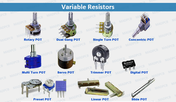
Variable Resistors
Variable resistors can be simply categorized into three types:
- Potentiometers
- Rheostats
- Digital potentiometers
Potentiometer
Potentiometers are used to vary the resistance in a circuit by turning a rotary knob. Potentiometers have three pins. Between the two side pins, there is a strip of resistive material and this material creates resistance. The middle pin is the wiper. This wiper connection is somewhere on the strip between the two ends. You can move the point where the wiper connects to the resistive material by turning the shaft of the potentiometer. When moving the wiper to the left side, there is a decrease in resistance between the middle pin and the left pin. Then, the resistance between the middle pin and the right pin increases upon moving the wiper to the left side.
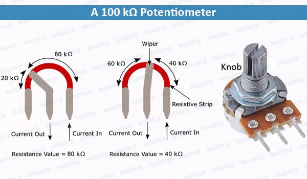
A 100 kΩ Potentiometer
Types of Potentiometers
- Rotary Potentiometers – the most common type of potentiometer. They use a rotary knob to move the wiper around the resistive material.
- Linear Potentiometers – consist of a linear slider that controls the position of the wiper along the resistive material.
Potentiometers Are Like Voltage Dividers
A voltage divider is a simple circuit that can be used to reduce the voltage in a circuit. The output voltage depends on the ratio of two resistors connected in series. The output voltage is taken from a point between the two resistors. To calculate the output voltage of a voltage divider, use the Voltage Divider Equation below:
Vout=R2/(R1+R2 ) x Vin
R1 is the resistor closest to the input voltage, R2 is the resistor closest to ground, Vin is the input voltage, and Vout is the output voltage.
Potentiometers are basically just adjustable voltage dividers. Internal to the potentiometer is a single resistor and a wiper that cuts the resistors into two and moves to adjust the ratio between both halves. Externally, there are usually three pins: two pins connect to each end of the resistor, while the third connects to the potentiometer’s wiper. If the two outside pins are connected to a voltage, the output (Vout at the middle pin) will mimic a voltage divider. If the potentiometer will turn all the way in one direction, the voltage be zero. And if it turns to the other side, the output voltage approaches the input and a wiper in the middle position means the output voltage will be half of the input.
Wiring A Potentiometer
- Begin by identifying the three terminals on the potentiometer. Position it with the shaft facing up and the three terminals are facing towards you. In this position, you can easily identify the terminals from left to right as terminal 1, 2, and 3. Ground the first terminal of the potentiometer.
- In this application, terminal 1 will provide the grounding. To do this, solder both ends of the wire to the terminal and chassis of the electrical component respectively. Measure and cut the length of the wire you will need to connect the terminal to a convenient location on the chassis and solder both ends of the wire to terminal and to the component’s chassis. This will ground the potentiometer. And it can be turned all the way to zero at the minimum position.
- Wire the second terminal to the circuit’s output to create the potentiometer’s input. The input line from the circuit should connect to it. Solder this connection just like the previous one.
- Wire terminal 3 to the circuit’s input since terminal 3 is the potentiometer’s output. Solder the wire just like in the first 2 terminals.
- After wiring, test using a voltmeter. Connect the voltmeter’s leads to the input and output terminals of the potentiometer and turn on the shaft. Turning the shaft clockwise or counterclockwise can adjust the signal on your device.
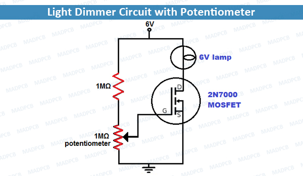
Light Dimmer Circuit with Potentiometer
Digital Potentiometer
A digital potentiometer is a type of variable resistor that uses digital signals instead of mechanical motion to change its resistance. Digital potentiometers change resistance in discrete steps depending on the digital signal sent to it. They’re great for environments where vibration, dust, or moisture would gum up the shaft of a mechanical potentiometer.
There are some digital potentiometers that are popular with electronics hobbyists:
Each of the following digital potentiometers are from Renesas Electronics and have 100 different resistance points, operate on 5V, and are controlled with a three-wire serial interface:
- X9C102 – 1kΩ
- X9C103 – 10kΩ
- X9C503 – 50kΩ
- X9C104 – 100kΩ
The MPC41/42 family of digital potentiometers from Microchip are also fairly common:
- MCP4131 – 129 resistance points, available in 5kΩ, 10kΩ, 50kΩ and 100kΩ, operating voltage of 1.8V to 5.5V, controlled with SPI
- MCP42010 – 256 resistance points, available in 10kΩ, 50kΩ, and 100kΩ, operating voltage of 2.7V to 5.5V, controlled with SPI
Combine Potentiometer into Carbon Ink Printed PCB
More and more PCB designs adopts conductive carbon ink printing process to replace a potentiometer and combine it into the PCBs, including rigid board, flex circuit and rigid-flex board. The main requirements on such PCBs include carbon resistance (R), sheet resistance (R□), and linear tolerance (like 10%).
Excepts for carbon ink, silver ink and copper paste are also common demands in some special designs, but with expensive manufacturing costs. Want to customize such printed circuit boards? Just contact MADPCB for technical assistance and quick quote.