What is Ground?
In electronics and electrical engineering, it is by convention we define a point in a circuit as a reference point. This reference point is known as Ground (GND) and carries a voltage of 0V. Voltage measurements are relative measurements. That is, a voltage measurement must be compared to another point in the circuit. If it is not, the measurement is meaningless.
For any electrical circuit to function, it must be a closed circuit, there must always be a way for current to return to the source. Regardless of how complex a circuit becomes, there will be either a trace(s) or a plane that serves as the return path for the current to get back to the source.
Typically, this reference point is the base for all other voltage measurements within the circuit. However, not all voltage measurements are taken from this reference point.
In almost all circuits, these return paths are collectively called “ground”. The problem with this is that the term “ground” is also used to define the reference point for the circuit.
The reference point is necessary because there is no such thing as an absolute zero voltage. When you measure a voltage, it is always relative to some reference node in your PCB design, and it doesn’t necessarily have to be on the return path. In fact, from a theoretical perspective any node in your circuit can be the reference node, however for reasons we will get into later some nodes are better than others.
Earth Ground
Earth (the soil beneath our feet, not the planet) is considered an infinite source of electrons and defines the reference point for all the electrical wiring in our homes. In practical terms, this return path is “connected” by driving a metal rod into the ground and making sure that all the “ground” wiring in our homes bonds(connects) solidly to it.
Chassis Ground
This type of ground gets its name when the metal enclosure of a device is defined as a reference point for an electrical circuit. The main reason for using the chassis of an enclosure and the earth as reference points has to do with safety. Our bodies are almost always at earth potential (or very nearly so). Imagine, for a moment that you are going to do your laundry, inside your washing machine all the electronics are connected to the chassis (chassis ground) and the chassis is connected to the ground plug of your outlet (earth ground).
Again, if we think in terms of return paths, you’ll see that in this example the chassis ground and earth ground from a return path to the AC source. This avoids a difference in potential between your body and the washer’s enclosure which would cause current to flow through your body.
Signal Ground
This is the most common designation and it’s basically a definition of the reference node for the circuits on our printed circuit boards (PCBs). Usually, it is physically implemented using a ground plane, that way there is a low impedance return path to the power source in PCB design. This is important otherwise different “grounds” on the board may be at different potentials (the reference node doesn’t have the same value everywhere) and this could cause the circuit to malfunction or just not work period.
Analog and Digital Grounds
Digital circuits generate spikes of current when the digital signals change states. When load currents change in analog circuits, current spikes are generated again.
Although there are multiple techniques for proper grounding, when it comes to mixed-signal grounding it’s of most importance—regardless of which grounding technique is adopted—to separate the “more-noisy” digital return currents from the “less-noisy” analog return currents. This separation of the grounds helps to minimize or prevent noise from being generated within circuits due to ground currents.
Such ground currents—think of them as changing currents—when applied to ground return paths, create voltage variations (recall Ohm’s Law) called noise. You may have heard the term “a noisy ground.” Such noise can compromise sensitive signals in local circuits. Grounding has always been a major obstacle for design, system, and test engineers.
One possible grounding technique, which can be helpful in some, but not all, situations, uses what is called a “star” ground. This philosophy builds on the theory that all voltages in a circuit are referred to a single ground point.
The method of using single grounding points (or star grounds) looks great on paper. In practice, however, it can be very difficult to implement depending on the complexity of one’s design. An alternative approach is to use a grounded bus bar.
Keep in mind, though, that physically separating analog and digital grounds is generally not required because return currents can be managed via proper PCB layout even when the design uses a single (shared) ground plane.
Common Grounding Error
A three-terminal DC power supply may be a little confusing to beginners. This power supply has a positive (+), a negative (-), and a GND (ground) terminal. As mentioned previously, the ground terminal (earth ground) is physically tied to the chassis, which in turn is connected to the ground wire within the power cord, which is finally connected to the earth via the three-prong outlet.
A fairly common mistake made by beginners is to connect a load between the positive (+) and the GND terminals. This incorrect connection won’t allow the current to return to its energy source (the power supply itself), and, therefore, no current will flow. The proper connection is to connect the load between the positive (+) and negative (-) terminals.
Electrostatic Discharge (ESD)
The grounding of your test equipment also helps in the elimination of electrostatic discharge (ESD). ESD occurs when a statically-charged body comes in contact with the test equipment. Some test equipment is ultra-sensitive and may be very vulnerable to ESD events.
Integrated circuits (ICs) are notorious for being ultra-vulnerable to ESD events. Grounded mats (referred to as ESD mats), grounded chairs, and wrist straps provide adequate ESD protection for your ICs by grounding you—thus discharging any static you may have on your body—prior to touching any sensitive components. Most engineers and technicians also wear ESD-safe jackets when working with PCBs and ICs for added protection against possibly damaging components and equipment.
Do Really Need Ground?
As we have learned every single electrical system needs at least one return path back to the source, so in that sense, all circuits need a “ground”. Typically, this “ground” will also be used as the reference node against which all the voltages in the circuits can be measured. However, not all circuits connect to line voltages (i.e. battery powered devices), so they will not all need an earth “ground” or more correctly a return path through the earth. Similarly, devices in non-conductive enclosures don’t need a chassis return path for safety. What we need, is to be able call these paths something else to avoid confusion with ground.
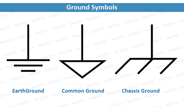
Ground Symbols
Now that you know what each of these types of “grounds” are it’s important to be able to recognize them in a schematic so that your electronics can work properly and in a safe manner. Below you will find the most commonly used symbols to represent a schematic that deviates from them. If this happens, please be sure to verify. Doing so will make sure that you are safe.