Impedance Control is the characteristic impedance of a transmission line formed by PCB traces and its associated reference planes. The impedance is the combination of the capacitance and the induction at high frequency. It is relevant when high frequency signals are propagation on the PCB transmission lines.
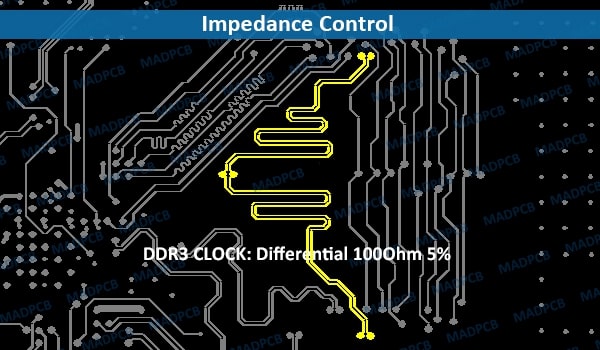
DDR3 CLOCK 100Ohm 5% Differential Impedance Control
Impedance control is important for solving SI (signal integrity) problems, which is the propagation of signal without distortion. When the PCB is manufactured, need to measure the impedance of certain traces and make sure they are within the tolerances (+/-10% or +/-5%) given by the designer. Impedance features in the following products, including:
- Analog and digital telecommunications
- Video signal processing
- Web boxes, TV, GPS, video games, digital cameras
- Computers, tablets, mobile phones
- Motor control modules
How Is Impedance Determined?
Usually, trace impedance depends on the following factors:
- Material’s dielectric constant
- Trace width and/or space, and thickness
- Core thickness, PP or PI thickness on each side of the trace
- Thickness from the reference copper plane
- Hatch width (HW) and hatch pitch (HP) -refer to Hatch Impedance
- Presence or not of solder mask or coverlay
Why Control Impedance on PCB?
When a signal needs a specific impedance to operate properly, controlled impedance should be preferred. In high frequency applications, keeping impedance constant on the complete electronic board is essential to protect the transferred data from damage and to maintain the clarity of the signal. The longer the trace or the higher the frequency, the more adaptation is needed. Any lack of rigor at this stage can increase the switching time for an electronic device or circuit and cause unexpected errors.
Uncontrolled impedance is difficult to analyze once the components are mounted on the circuit. Components have different tolerance capacities depending on their batch. Furthermore, their specifications are impacted by temperature variations which can lead to malfunctions. In such cases, replacing the component may seem to be the solution at first when, as a matter of fact, it is the unsuitable trace impedance that is the cause of the problem.
If a trace has been defined as an impedance control trace, it is not the trace size which is strictly defined, but rather the impedance. While a nominal trace size will be provided in the Gerber layer, it is understood the circuit board manufacturer can vary trace width, height, and dielectric thickness as long as the final impedance is within tolerance.
At MADPCB, we will check the impedance-controlled information in engineer query stage by impedance calculations. We will put impedance coupons on the waste tabs in our manufacturing panels. When the board manufacturing is finished, we will take off the coupons and measure them to check whether the impedances are met in tolerances.