What’s Hatch Impedance in Flex PCB Circuit?
When crosshatching (or meshed) return paths are deployed on flex PCBs and rigid-flex boards rather than the solid copper pour return paths of traditional rigid PCBs, the calculation of impedance of stripline and microstrip PCB traces requires Hatch Impedance Calculation.
The shortcomings of crosshatch or mesh as a high frequency return path with all the implications of lengthened returned path, etc. are well understood; however, the use of crosshatched planes on flex and flex-rigid PCBs have proved a practical method of keeping controlled impedance traces at wider, more manufacturable dimensions while also achieving the desired flexibility of the PCB assembly.

Hatch Impedance in Flex-Rigid and Flex PCB
Hatch Impedance calculation
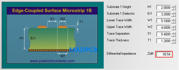
From the field solver, you may notice the reference plane layer is crosshatching copper, but not solid copper pouring. Find MADPCB to make your flexible circuits, we will make the stack-up and calculations together with the quick quote. When it comes to working Gerber stage, we absolutely add impedance test coupons for further actual measurement.
Relationship between Cross Hatch Plane and Impedance
There are other concerns that must be weighed before specifying a cross hatch plane on a flex circuit. If your application requires impedance control, the crosshatch plane will have a significant impact on the impedance value. Without going through all of the impedance formula and calculations, know that impedance is directly affected by the capacitance that is created between the transmission line and its return path (the copper plane).
As capacitance decreases, impedance increases. Because capacitance is driven by the area and distance between the two conductors, decreasing the amount of copper in the return path (cross hatched plane) decreases the capacitance. This serves to increase the characteristic impedance of the transmission line.
Sounds like a great way to increase impedance without making the flex circuit any thicker, right? Not really.
- We are not aware of an impedance calculator that takes into account a cross hatched plane. All assume a solid fill on plane layers. The reason is that, for the most part, only the flex circuit industry uses crosshatched planes. This is done almost exclusively to make a flex circuit more flexible. Rigid PCB users are not concerned with flexibility, so there is no reason to use anything but a solid shield. While the flex circuit industry is growing, it still does not represent a large enough market for anyone to do the monumental amount of testing required to develop a calculator that includes a variable for cross hatched planes.
- Also, the path the transmission line follows under the crosshatching pattern can vary widely depending on the pattern and orientation. Two conductors running side by side may have significantly different characteristic impedances depending on how much of the plane copper they can couple. It would be virtually impossible to include all of the possible variations of cross hatch patterns and signal trace orientation in an impedance calculator program.
If you believe your PCB design may be too stiff to function properly, and you have impedance control issues, you may need to consider selectively bonding substrates in the flexing area. Selectively bonding or “unbonding” portions of the flexing area will have a much bigger impact on the flexibility than a cross hatch plane. Remember, when a selectively bonded circuit is flexed, the unbonded areas will buckle, creating a space between substrates.
Therefore, the designer must carefully select which substrates will be unbonded to ensure that all signal and return path planes are bonded to each other. If a signal layer is not bonded to its plane layer(s), the space created when the circuit buckles will result in an impedance mismatch in that area. When done properly, selective bonding can significantly increase flexibility without affecting electrical performance. If your planes are only used as a return path for slower signals or for noise control, crosshatching alone can be used effectively to increase flexibility.