What Is A PCB Microstrip?
PCB Microstrip is a type of electrical transmission line which can be fabricated with any technology where a conductor is separated from a ground plane by a dielectric layer known as FR4, polyimide, PP, Coverlay. Microstrips are used to convey microwave-frequency signal.
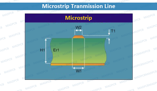
Microstrip Transmission Line
Advantages and Disadvantages of Microstrip
Microstrips in printed circuit board (PCB) is a typical application. Microwave components, such as antennas, couplers, filters, power dividers etc. can be formed from microstrip on circuit boards, with the entire device existing as the pattern of metallization on the substrate. Microstrip is thus much less expensive than traditional waveguide technology, as well as being far lighter and more compact.
The disadvantages of microstrip compared with waveguide are the generally lower power handling capacity, and higher losses. Also, unlike waveguide, microstrip is typically not enclosed, and is therefore susceptible to cross-talk and unintentional radiation.
For lowest cost, microstrip devices may be built on an ordinary FR-4 (standard PCB) substrate. However, it is often found that the dielectric losses in FR4 are too high at microwave frequencies, and that the dielectric constant is not sufficiently tightly controlled. For these reasons, an alumina substrate is commonly used. From monolithic integration perspective microtrips with integrated circuit/monolithic microwave integrated circuit technologies might be feasible however their performance might be limited by the dielectric layer(s) and conductor thickness available.
Microstrip lines are also used in high-speed digital PCB designs, where signals need to be routed from one part of the assembly to another with minimal distortion, and avoiding high crosstalk and radiation.
Microstrip is one of many forms of planar transmission line, others include stripline and coplanar waveguide, and it is possible to integrate all of these on the same substrate.
A differential microstrip—a balanced signal pair of microstrip lines—is often used for high-speed signals such as DDR2 SDRAM clocks, USB Hi-Speed data lines, PCI Express data lines, LVDS data lines, etc., often all on the same PCB. Most PCB design tools support such differential pairs.
The electromagnetic wave carried by a microstrip line exists partly in the dielectric substrate, and partly in the air above it. In general, the dielectric constant of the substrate will be different (and greater) than that of the air, so that the wave is travelling in an inhomogeneous medium. In consequence, the propagation velocity is somewhere between the speed of radio waves in the substrate, and the speed of radio waves in air. This behavior is commonly described by stating the effective dielectric constant (or effective relative permittivity) of the microstrip; this being the dielectric constant of an equivalent homogeneous medium (i.e., one resulting in the same propagation velocity).
Further consequences of an inhomogeneous medium include:
- The line will not support a true TEM wave; at non-zero frequencies, both the E and H fields will have longitudinal components (a hybrid mode). The longitudinal components are small however, and so the dominant mode is referred to as quasi-TEM. The line is dispersive. With increasing frequency, the effective dielectric constant gradually climbs towards that of the substrate, so that the phase velocity gradually decreases. This is true even with a non-dispersive substrate material (the substrate dielectric constant will usually fall with increasing frequency).
- The characteristic impedance of the line changes slightly with frequency (again, even with a non-dispersive substrate material). The characteristic impedance of non-TEM modes is not uniquely defined, and depending on the precise definition used, the impedance of microstrip either rises, falls, or falls then rises with increasing frequency. The low-frequency limit of the characteristic impedance is referred to as the quasi-static characteristic impedance, and is the same for all definitions of characteristic impedance.
- The wave impedance varies over the cross-section of the line.
- Microstrip lines radiate and discontinuity elements such as stubs and posts, which would be pure reactances in stripline, have a small resistive component due to the radiation from them.