What is an Electrical Network?
An Electrical Network, also known as Electrical Circuit, or Electric Circuit) is an interconnection of various active and passive components (e.g., batteries, resistors, inductors, capacitors, switches, transistors) or a model of such an interconnection, or a model of such an interconnection, consisting of electrical elements (e.g., voltage sources, current sources, resistances, inductances, capacitances), in a prescribed manner to form a closed path. An electrical circuit is a network consisting of a closed loop, giving a return path for the current.
Linear electrical networks, a special type consisting only of sources (voltage or current), linear lumped elements (resistors, capacitors, inductors), and linear distributed elements (transmission lines), have the property that signals are linearly superimposable. They are thus more easily analyzed, using powerful frequency domain methods, such as Laplace transforms, to determine DC response, AC response, and transient response.
Electrical Network
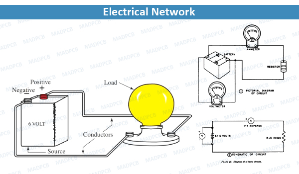
The main parts of an ideal electric circuit are:
- Electrical sources for delivering electricity to the circuit and are mainly electric generators and batteries
- Controlling devices for controlling electricity and are mainly switches, circuit breakers, MCBs, and potentiometer-like devices, etc.
- Protection devices for protecting the circuit from abnormal conditions and are mainly electric fuses, MCBs, switchgear systems.
- Conducting path to carry electric current from one point to other in the circuit and these are mainly wires or conductors.
Classification
- By passivity: An active network contains at least one voltage source or current source that can supply energy to the network indefinitely. A passive network does not contain an active source. An active network contains one or more sources of electromotive force. Practical examples of such sources include a battery or a generator. Active elements can inject power to the circuit, provide power gain, and control the current flow within the circuit. Passive networks do not contain any sources of electromotive force. They consist of passive elements like resistors and capacitors.
- By linearity: A network is linear if its signals obey the principle of superposition; otherwise, it is non-linear. Passive networks are generally taken to be linear, but there are exceptions. For instance, an inductor with an iron core can be driven into saturation if driven with a large enough current. In this region, the behavior of the inductor is very non-linear.
- By lumpiness: Discrete passive components (resistors, capacitors and inductors) are called lumped elements because all of their, respectively, resistance, capacitance and inductance are assumed to be located (“lumped”) at one place. This design philosophy is called the lumped-element model and networks so designed are called lumped-element circuits. This is the conventional approach to circuit design. At high enough frequencies, or for long enough circuits (such as power transmission lines), the lumped assumption no longer holds because there is a significant fraction of a wavelength across the component dimensions. A new design model is needed for such cases called the distributed-element model. Networks designed to this model are called distributed-element circuits. A distributed-element circuit that includes some lumped components is called a semi-lumped design. An example of a semi-lumped circuit is the comblined filter.
Applying Electrical Laws
A number of electrical laws apply to all linear resistive networks. These include:
- Kirchhoff’s current law: The sum of all currents entering a node is equal to the sum of all currents leaving the node.
- Kirchhoff’s voltage law: The directed sum of the electrical potential differences around a loop must be zero.
- Ohm‘s law: The voltage across a resistor is equal to the product of the resistance and the current flowing through it.
- Norton’s theorem: Any network of voltage or current sources and resistors is electrically equivalent to an ideal current source in parallel with a single resistor.
- Thévenin’s theorem: Any network of voltage or current sources and resistors is electrically equivalent to a single voltage source in series with a single resistor.
- Superposition theorem: In a linear network with several independent sources, the response in a particular branch when all the sources are acting simultaneously is equal to the linear sum of individual responses calculated by taking one independent source at a time.
Applying these laws results in a set of simultaneous equations that can be solved either algebraically or numerically. The laws can generally be extended to networks containing reactance. They cannot be used in networks that contain nonlinear or time-varying components.
Thus, voltage and current are the two basic features of an electric element. Various techniques by which voltage and current across any element in any electric circuit are determined is called electric circuit analysis.
Basic Properties of Electrical Network
The basic properties of electric circuits include:
- A circuit is always a closed path.
- A circuit always contains at least an energy source that acts as a source of electrons.
- The electric elements include an uncontrolled and controlled source of energy, resistors, capacitors, inductors, etc.
- In an electric circuit flow of electrons takes place from the negative terminal to the positive terminal.
- The direction of flow of conventional current is from positive to negative terminal.
- The flow of current leads to a potential drop across the various elements.
Types of Electric Networks
The main types of electric circuits are:
- Open circuit: If due to disconnection of any part of an electric circuit if there is no flow of current through the circuit, is said to be an open circuited.
- Closed circuit: If there is no discontinuity in the circuit and current can flow from one part to another part of the circuit, the circuit is said to be closed circuit.
- Short circuit: If two or more phases, one or more phases and earth or neutral of AC system or positive and negative wires or positive or negative wires and earth of DC system touch together directly or connected together by a zero impedance path then the circuit is said to be short circuited.
- Series Circuit: When all elements of a circuit are connected one after another in tail to head fashion and due to which there will be only one path of flowing current then the circuit is called series circuit. The circuit elements then are said to be series-connected. In the series electrical circuit, the same current flows through all elements connected in the series.
- Parallel Circuit: If components are connected in such a way that the voltage drop across each component is same then it is known as parallel circuit. In parallel circuit the voltage drop across each component is same but the currents flowing through each component may differ. The total current is the sum of currents flowing through each element. An example of a parallel circuit is the wiring system of a house. If one of the electric lamp burn out, current can still flow through the rest of the lights and appliances. In a parallel circuit the voltage is the same for all elements.
- Series Parallel Circuit: An electrical circuit in which some of the elements are connected in series and some of the elements are connected in parallel is called a series-parallel circuit. Most of the practical circuits are series-parallel circuits. A very common example is the connection of conductors in the rotor of the DC motor.