Oscilloscope Introduction
An oscilloscope, previously called an oscillograph, and informally known as a scope or o-scope, CRO (for cathode-ray oscilloscope), or DSO (for the more modern digital storage oscilloscope), is a type of electronic test instrument that graphically displays varying signal voltages, usually as a calibrated two-dimensional plot of one or more signals as a function of time. The displayed waveform can then be analyzed for properties such as amplitude, frequency, rise time, time interval, distortion, and others. Originally, calculation of these values required manually measuring the waveform against the scales built into the screen of the instrument. Modern digital instruments may calculate and display these properties directly.
Oscilloscope
The oscilloscope can be adjusted so that repetitive signals can be displayed as persistent waveforms on the screen. A storage oscilloscope can capture a single event and display it continuously, so the user can observe events that would otherwise appear too briefly to be seen directly.
Oscilloscopes are used in the sciences, medicine, engineering, automotive and the telecommunications industry. General-purpose instruments are used for maintenance of electronic equipment and laboratory work. Special-purpose oscilloscopes may be used to analyze an automotive ignition system or to display the waveform of the heartbeat as an electrocardiogram, for instance.
Early oscilloscopes used cathode ray tubes (CRTs) as their display element (hence they were often referred to as CROs) and linear amplifiers for signal processing. Storage oscilloscopes used special storage CRTs to maintain a steady display of a single brief signal. CROs were later largely superseded by digital storage oscilloscopes (DSOs) with thin panel displays, fast analog-to-digital converters and digital signal processors. DSOs without integrated displays (sometimes known as digitizers) are available at lower cost and use a general-purpose computer to process and display waveforms.
History
The Braun tube was known in 1897, and in 1899 Jonathan Zenneck equipped it with beam-forming plates and a magnetic field for sweeping the trace. Early cathode ray tubes had been applied experimentally to laboratory measurements as early as the 1920s, but suffered from poor stability of the vacuum and the cathode emitters. V. K. Zworykin described a permanently sealed, high-vacuum cathode ray tube with a thermionic emitter in 1931. This stable and reproducible component allowed General Radio to manufacture an oscilloscope that was usable outside a laboratory setting. After World War II surplus electronic parts became the basis for the revival of Heathkit Corporation, and a $50 oscilloscope kit made from such parts proved its premiere market success.
Features and Uses
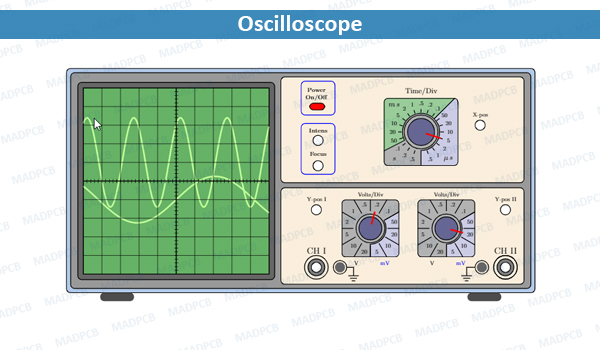
An analog oscilloscope is typically divided into four sections: the display, vertical controls, horizontal controls and trigger controls. The display is usually a CRT with horizontal and vertical reference lines called the graticule. CRT displays also have controls for focus, intensity, and beam finder.
The vertical section controls the amplitude of the displayed signal. This section has a volts-per-division (Volts/Div) selector knob, an AC/DC/Ground selector switch, and the vertical (primary) input for the instrument. Additionally, this section is typically equipped with the vertical beam position knob.
The horizontal section controls the time base or “sweep” of the instrument. The primary control is the Seconds-per-Division (Sec/Div) selector switch. Also included is a horizontal input for plotting dual X-Y axis signals. The horizontal beam position knob is generally located in this section.
The trigger section controls the start event of the sweep. The trigger can be set to automatically restart after each sweep, or can be configured to respond to an internal or external event. The principal controls of this section are the source and coupling selector switches, and an external trigger input (EXT Input) and level adjustment.
In addition to the basic instrument, most oscilloscopes are supplied with a probe. The probe connects to any input on the instrument and typically has a resistor of ten times the oscilloscope’s input impedance. This results in a .1 (‑10X) attenuation factor; this helps to isolate the capacitive load presented by the probe cable from the signal being measured. Some probes have a switch allowing the operator to bypass the resistor when appropriate.