What is Polarity?
In electronics, Polarity indicates whether a circuit component is symmetric or not. Polarity is a very important concept, especially when it comes to physically building circuits. Whether you’re plugging parts into a breadboard, soldering them to a printed circuit board (PCB), or sewing them into an e-textile project, it’s critical to be able to identify polarized components and to connect them in the correct direction.
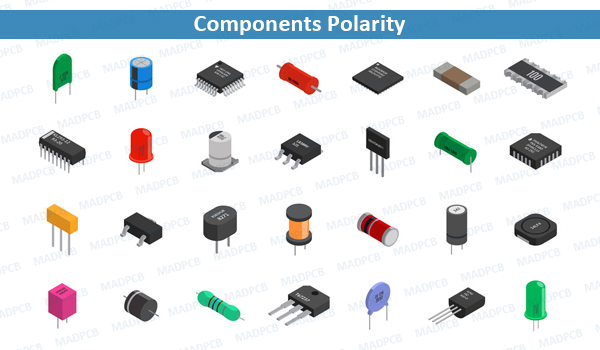
Components Polarity
Which components do and don’t have polarity? How to identify component polarity? And how to test some components for polarity?
- Non-polarized component: a part without polarity – can be connected in any direction and still function the way it’s supposed to function. A symmetric component rarely has more than two terminals, and every terminal on the components is equivalent. You can connect a non-polarized component in any direction, and it’ll function just the same.
- Polarized component: a part with polarity – can only be connected to a circuit in one direction. A polarized component might have two, twenty, or even two-hundred pins, and each one has a unique function and/or position. If a polarized component was connected to a circuit incorrectly, at best it won’t work as intended. At worse, an incorrectly connected polarized component will smoke, spark, and be one very dead part.
Some Simple Non-polarized Examples
So called passive components like resistors, capacitors and inductors are generally not polarized. There are of course exceptions to that rule.
- Special case Capacitors: Not all capacitors are polarized, but when they are, it’s very important not to mix up their polarity. Ceramic capacitors– the small (typically 1µF and less), commonly blue or yellow colored ceramic bodies – are not polarized. You can connect those either way in the circuit. Through-hole and SMD 0.1µF ceramic capacitors. These are NOT polarized.
- Electrolytic and Tantalum Capacitors: Electrolytic capacitors (they contain electrolytes), which look like little tin cans, are polarized. The negative pin of the capacitor is usually indicated by a (-) marking, and/or a colored strip along the can. They might also have a longer positive leg. Below is an electrolytic capacitor which has a dash symbol to mark the negative leg, as well as a longer positive leg and a tantalum capacitor.
Applying a negative voltage for an extended period to a polarized electrolytic or tantalum capacitor will result in a briefly exciting, but catastrophic, failure. They’ll make a pop, and the top of the cap will either swell or burst open. Tantalum capacitors can even catch on fire. From then on the cap will be as good as dead, acting like a short circuit.
Polarized Components
- Batteries and Power Supplies: Getting polarity right in your circuit starts and ends with getting the power supply connected correctly. Whether your project is getting power from a wall powered supply, it is critical to make sure you do not accidently connect the positive and negative terminals backwards. Anyone that has ever replaced batteries knows how to find their polarity. Most batteries will indicate the positive and negative terminals with a “+” or “-” symbol. Other indicators of polarity might be the color of the wires, red for positive and black for negative. All batteries. Lithium polymer, coin cell, 9V alkaline, AA alkaline, and AA NiMH have some way to represent the positive and negative terminals. Power supplies usually have a standardized connector, which should usually have polarity itself. A barrel jack, for example, has two conductors: outer and inner; the inner/center conductor is usually the positive terminal. Other connectors, have keys so you they cannot be inserted backwards. For extra protection against reversing power supply polarity, you can add reverse polarity protection using a diode, or a MOSFET.
- Diode Polarity: Diodes are two terminal components that only allow current to flow in one direction, and they are always polarized. The positive terminal (+) is called the anode, and the negative terminal is called the cathode. Current through a diode can only flow from the anode to the cathode, which would explain why it’s important for a diode to be connected in the correct direction. Physically, every diode should have some sort of indication for either the anode or cathode pin. Usually, the diode will have a line near the cathode pin, which matches the vertical line in the diode circuit symbol.
- Light Emitting Diodes, LEDs: LED stands for light-emitting diode, which means that much like other normal diodes, they’ are polarized. There are a handful of identifiers for distinguishing the positive and negative pins on an LED. One is to identify the longer leg, which should indicate the positive, anode pin. Sometimes the leads have been trimmed, try finding the flat edge on the LED’s outer casing. The pin nearest the flat edge will be the negative, cathode pin. There might be other indicators as well. SMD diodes have a range of anode/cathode identifiers. Sometimes it’s easiest to just use a multi-meter to test for polarity. Turn the multi-meter to the diode setting (usually indicated by a diode symbol), and touch each probe to one of the LED terminals. If the LED lights up, the positive probe is touching the anode, and the negative probe is touching the cathode. If it doesn’t light up, try swapping the probes around. Some LEDs like Blue or White LEDs with higher forward voltages will not light in either direction using the diode test function on a multi-meter.
- Transistors, MOSFETs, and Voltage Regulators: These (traditionally) three-terminal, polarized components are lumped together because they share similar package types. Through-hole transistors, MOSFETs, and voltage regulators commonly come in a TO-92 or TO-220 package, seen below. To find which pin is which, look for the flat edge on the TO-92 package or the metal heatsink on the TO-220, and match that up to the pin-out in the datasheet. Above, a 2N3904 transistor in a TO-92 package, note the curved and straight edges. Devices in a TO-220 package can have two, three or more leads. An adjustable regulator in a TO-220 package, note the metal heatsink TAB on the back. This is just the tip of the polarized-component iceberg. Even non-polarized components, like resistors, can come in multi-lead packages. A resistor pack – a grouping of five-or-so pre-arranged resistors – is one such example.
- Resistor arrays: A SIP resistor pack, is an array of five 330Ω resistors, all tied together at one end. The dot represents the first, common pin. The resistors in side are not individually “polarized” but the common connection makes the overall array non-symmetric. A SIP resistor pack, is an array of five 330Ω resistors, all tied together at one end. The dot represents the first, common pin. The resistors in side are not individually “polarized” but the common connection makes the overall array non-symmetric.
Finding a reliable turnkey PCB and assembly manufacturer with low cost in China? Get in touch with our professional sales engineer to get quick quote for your BOM cost, assembly cost, tooling cost and PCB cost now.