What’s A Voltage Regulator?
Power Regulator is the power supply unit of an electronic device converts incoming power into the desired type (AC-DC or DC-DC) and desired voltage/current characteristics. A voltage regulator is a component of the power supply unit that ensures a steady constant voltage supply through all operational conditions. It regulates voltage during power fluctuations and variations in loads. It can regulate AC as well as DC voltages.
Voltage Regulators
All electronic devices are designated to run at predetermined power ratings, i.e. voltage and current. While current consumption is dynamic and depends on the device load, the voltage supply is fixed ideally constant for the proper functioning of the device. A voltage regulator is responsible to maintain this ideal voltage needed for the device. Your laptop, wall charge, and coffee maker all have voltage regulators.
A voltage regulator usually takes in higher input voltage and emits a lower, more stable output voltage. Their secondary use is also to protect the circuit against voltage spikes that can potentially damage/fry them.
Different Types of Voltage Regulators
Voltage regulators used in low-voltage electronic devices are usually integrated circuits (ICs). Power distribution centers providing AC power to residential and industrial consumers use more sophisticated and mechanically large voltage regulators that maintain rated 110V, 220V, 250V, 380V voltage regardless of consumption demands across the area.
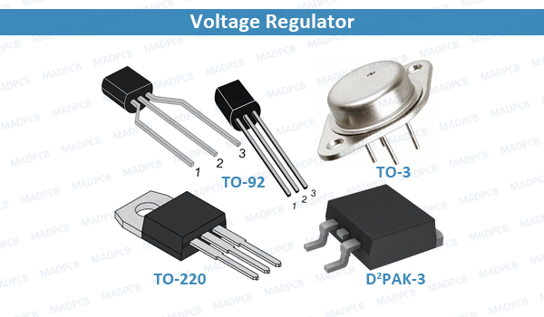
Based on the physical design, voltage regulators can be seen in integrated circuits, electromechanical devices, or solid-state automatic regulators. The most common classifications of the active voltage regulators (that use amplifying components like transistors or op-amps) are linear and switching regulators.
- Linear Regulators: A linear voltage regulator utilizes an active pass device (such as a BJT or MOSFET), which is controlled by a high-gain operational amplifier. To maintain a constant output voltage, the linear regulators adjust the pass device resistance by comparing the internal voltage reference to the sampled output voltage, and then driving the error to zero. Linear regulators are step-down converters, so by definition the output voltage is always below the input voltage. However, these regulators offer a few advantages: they are generally easy to design, dependable, cost-efficient, and offer low noise as well as a low output voltage ripple.
- Switching Regulators: A switching regulator circuit is generally more complicated to design than a linear regulator, and requires selecting external component values, tuning control loops for stability, and careful layout design. Switching regulators can be step-down converters, step-up converters, or a combination of the two, which makes them more versatile than a linear regulator. Advantages of switching regulators include that they are highly efficient, have better thermal performance, and can support higher current and wider Vin/Vout applications. They can achieve greater than 95% efficiency depending on the application requirements. Unlike linear regulators, a switching power supply system may require additional external components, such as inductors, capacitors, PETs, or feedback resistors.
Limitations of Voltage Regulators
One of the main disadvantages for linear regulators is that they can be inefficient, as they dissipate large amounts of power in certain use cases. The voltage drop of a linear regulator is comparable to a voltage drop across a resistor. For instance, with a 5V and a 3V output voltage, there is a 2V drop between the terminals, and the efficiency is limited to 3V/5V (60%). This means linear regulators are best suited for applications with lower Vin/Vout differentials.
It is important to consider the estimated power dissipation of a linear regulators in application, since using larger input voltage results in high power dissipation that can overheat and damage components.
Another limitation of linear voltage regulator is that they are only capable of buck (step-down) conversion, in contrast to switching regulators, which also offer boost (step-up) and buck-boost conversion.
Switching regulators are highly efficient, but some disadvantages include that they are generally less cost-effective than linear regulators, larger in size, more complex, and can create more noise if their external components are not carefully selected. Noise can be very important for a given application, as noise can affect circuit operation and performance, as well as EMI performance.
Switching Regulator Topologies: Step-Down, Step-Up, Linear, LDO, and Adjustable
There are various topologies for linear and switching regulator. Linear regulators often reply on low-dropout (LDO) topologies. For switching regulators, there are three common topologies: step-down convertors, step-up converters, and buck-boost converters. Each topology described below:
- LDO Regulators: One popular topology for linear regulators is a low-dropout (LDO) regulator. Linear regulators typically require the input voltage to be at least 2V above the output voltage. However, an LDO regulator is designed to operate with a very small voltage difference between input and output terminals, sometimes as low as 100mV.
- Step-Down and Step-Up Converters: Step-down converters (also called buck converters) take a larger input voltage and produce a lower output voltage. Conversely, step-up converters (also called boost converters) take a lower input voltage and produce a higher output voltage.
- Buck-Boost Converters: A buck-boost converter is a single-stage converter that combines the functions of a buck and a boost converter to regulate the output over a wide range of input voltages that can be greater or less than the output voltage.
Voltage Regulator Control
The four fundamental components of a linear regulators are a pass transistor, error amplifier, voltage reference, and resistor feedback network. One of the inputs to the error amplifier is set by two resistors (R1 and R2) to monitor a percentage of the output voltage. The other input is a stable voltage reference (VREF). If the sampled output voltage changes relative to VREF, the error amplifier changes the pass transistor’s resistance to maintain a constant output voltage (VOUT). Linear regulators typically only require an external input and output capacitor to operate, making them easy to implement.
On the other hand, a switching regulator requires more components to create the circuit. The power stage switches between VIN and ground to create charge packets to deliver to the output. Similar to a linear regulator, there is an operational amplifier that samples the DC output voltage from the feedback network and compares it to an internal voltage reference. Then the error signal is amplified, compensated, and filtered. This signal is used to modulate the PWM duty cycle to pull the output into regulation. For example, if the load current increases rapidly and causes an output voltage droop, the control loop increases the PWM duty cycle to supply more charge to the load and bring the rail back into regulation.
Linear and Switching Regulator Applications
Linear regulators are often used in applications that are cost-sensitive, noise-sensitive, low-current, or space constrained. Some examples include consumer electronics such as headphones, wearables, and IoT devices. For instance, applications such as a hearing could use a linear regulator because they don’t have a switch element that could create unwanted noise and interfere with the device’s performance.
Moreover, if designers are mainly interested in creating a low-cost application, they need not be as concerned with power dissipation, and can rely on a linear regulator.
Switching regulators are beneficial for more general applications, and are especially useful in applications that need efficiency and performance, such as consumer, industrial, enterprise, and automotive applications. For example, if the application requires a large step-down solution, a switching regulator is better suited, since a linear regulator could create high power dissipation that would damage other electrical components.
Basic Parameters for a Voltage Regulator IC
Some of the basic parameters to consider when using a voltage regulator are the input voltage, output voltage, and output current. These parameters are used to determine which VR technology is compatible with a user’s IC.
Other parameter – including quiescent current, switching frequency, thermal resistance, and feedback voltage – may be relevant depending on the application.
Quiescent current is important when efficiency during light-load or standby modes is a priority. When considering switching frequency as a parameter, maximizing the switching frequency leads to smaller system solutions.
Additionally, thermal resistance is critical to remove heat from the device and dissipate it across the system. If the controller includes an internal MOSFET, then all losses (conductive and dynamic) are dissipated in the package and must be considered when calculating the maximum temperature of the IC.
Feedback voltage is another important parameter to examine because it determines the lowest output voltage that the voltage regulator can support. It is standard to look at the voltage reference parameters. This limits the lower output voltage, the accuracy of which impacts the accuracy of the output regulation.
How to Select Voltage Regulator for Your PCB?
To select the proper voltage regulator, the PCB designer must first understand their key parameters, such as VIN, VOUT, IOUT, system priorities (e.g, efficiency, performance and cost), and any additional key features, such as power good (PG) indication or enable control.
Once the designer has defined these requirements, use a parametric search table to find the best device to meet the desired printed circuit board (PCB) assembly requirements. The parameters search table is a valuable tool for designers, as it offers different features and packages available to meet the required parameters for your applications.
Every device comes with a datasheet that details what external parts are needed, and how to calculate their values to achieve an efficient, stable, and high-performance design. The datasheet can be used to calculate component values, such as output capacitance, output inductance, feedback resistance, and other key system components.