What Is a Resistive Power?
Resistive Power is that
- In a purely resistive circuit, all circuit power is dissipated by the resistor(s). Voltage and current are in phase with each other.
- In a purely reactive circuit, no circuit power is dissipated by the load(s). Rather, power is alternately absorbed from and returned to the AC source. Voltage and current are 90° out of phase with each other.
- In a circuit consisting of resistance and reactance mixed, there will be more power dissipated by the load(s) than returned, but some power will definitely be dissipated and some will merely be absorbed and returned. Voltage and current in such a circuit will be out of phase by a value somewhere between 0° and 90°.
What is the Resistive Circuit?
The power is wasted by the resistors in a completely resistive circuit, and the phase of the voltage and current stays the same, i.e. both the voltage and current reach their maximum value at the same moment. The resistor is a passive device that does not generate or use electricity. It is a device that turns electrical energy into heat.
The voltage-to-current ratio in an AC circuit is determined by the supply frequency, phase angle, and phase difference. In an AC resistive circuit, the value of the resistor’s resistance remains constant regardless of the supply frequency.
Let’s write the equation for the alternating voltage applied across the circuit:
V = Vmsin(ωt)
Then the current passing through the resistor will have the following instantaneous value:
I = V/R = Vmsin(ωt)/R
When ωt = 90o or sin(ωt) = 1, the present value will be at its highest. We can retrieve the value of sinωt by putting it into the above equation, so I = Imsin(ωt).
Phase Angle and Waveform of Resistive Circuit
It is obvious from the above equations that the applied voltage and the current flowing through a totally resistive circuit have no phase difference, i.e. the phase angle between voltage and current is zero. As a result, the current in an AC circuit with pure resistance is in phase with the voltage.
The waveform for the voltage reduction across the resistor is exactly in phase with the waveform for the current through it since the resistor simply and directly resists the flow of electrons at all times. We can compare the values of current and voltage at any point in time along the horizontal axis of the plot (any “snapshot” that looks at the quantities of a wave are known as instantaneous values, meaning the values at that point in time).
The instantaneous voltage across the resistor is also 0 when the instantaneous value for current is zero. Similarly, when the current through the resistor reaches its maximum value, the voltage across the resistor reaches its maximum value, and so on. Ohm’s Law holds for the instantaneous values of voltage and current at any point along the waves.
Power in Pure Resistive Circuit
In the power curve or waveform, the three colors red, blue, and pink represent the current, voltage, and power curves, respectively. The phasor diagram clearly shows that the current and voltage are in phase, which means that the current and voltage values reach their peaks at the same time, and the power curve is always positive for all current and voltage values.
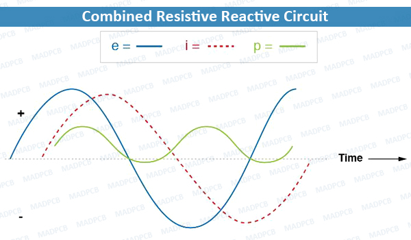
Combined Resistive Reactive Circuit
The Power in the Circuit is defined as the product of voltage and current in a DC supply circuit. The power is the same in both the AC and DC circuits; the only difference is that in the AC circuit, the instantaneous voltage and current values are taken into account. As a result, in a fully resistive circuit, the instantaneous power is given by the equation below (Instantaneous power, p= vi):
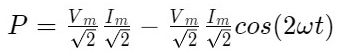
Instantaneous Power
The circuit’s average power consumption throughout a whole cycle is given by,

Average Power Consumption
Because the value of cosωt is zero. So, if you put the value of cosωt into the above equation, the value of power is defined as P=VRMSIRMS.
Where, P is the average power, VRMS is the root mean square value of supply voltage, and Ir.m.s is the root mean square value of the current. As a result, in a purely resistive circuit, the power is provided by P=VI.
In a purely resistive circuit, the voltage and current are in phase with each other, with no phase difference at phase angle zero. The alternating quantity reaches its maximum value at the same time interval, that is, the voltage and the current rise and decrease at the same time.
Reactive components, as we already know, dissipate no power since they absorb and return power to the rest of the circuit in equal amounts. As a result, any inductive reactance in this load dissipates zero power as well.
The resistive component of the load impedance is the only thing remaining to dissipate power. In the diagram below, we can understand how this combination works by looking at the waveform plot of voltage, current, and total power for this circuit.
The power dissipated by a combined resistive/reactive circuit is more than the power returned to the source. The resistor, on the other hand, wastes power, but the reactance does not. The power changes between positive and negative instantaneous values over time, as it does in every reactive circuit.
The oscillation between positive and negative power is evenly split in a fully reactive circuit, resulting in zero net power dissipation. The power waveform will still alternate between positive and negative in circuits with combined resistance and reactance, such as this one, but the amount of positive power will outweigh the amount of negative power. To put it another way, the combined inductive/resistive load will use more energy than it returns to the source.
When looking at the power waveform plot, it should be clear that the wave spends more time on the positive side of the centerline than on the negative side, suggesting that the load absorbs more power than is returned to the circuit.
The reactance is responsible for the little amount of power that returns; the imbalance of positive against negative power is caused by the resistance, which wastes energy outside of the circuit (usually in the form of heat). The quantity of mechanical energy required to move the shaft if the source were a mechanical generator would be the power averaged between the positive and negative power cycles.
Because the power wave is not at the same frequency as voltage or current, mathematically expressing power in an AC circuit is difficult. Furthermore, the phase angle for power differs significantly from the phase angle for voltage or current. The phase angle for power represents a ratio between power dissipated and power recovered, whereas the phase angle for voltage or current reflects a relative change in the time between two waves.
Because of how AC power varies from AC voltage or current, calculating power with scalar quantities of voltage, current, resistance, and reactance is actually easier than trying to derive it from vectors, or complex quantities of voltage, current, and impedance that we’ve worked with so far.