What Is A Silicon Controlled Switch?
A Silicon Controlled Switch (SCS) is a unilateral, four-layer three junction P-N-P-N silicon device with four electrodes namely cathode C, cathode gate GX, anode gate G2, and the anode A. The SCS is a low power device, which handles currents in milliamperes (mA) rather than amperes (A).
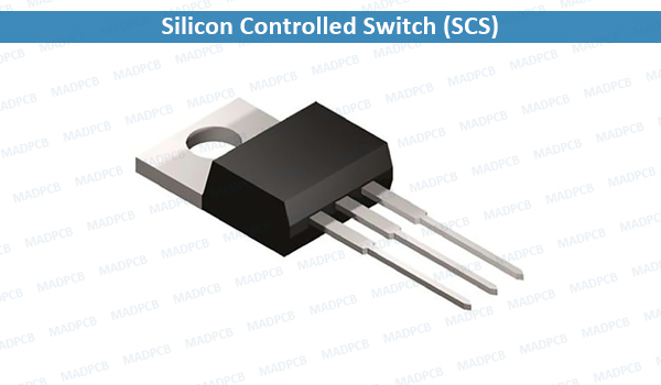
Silicon Controlled Switch (SCS)
Operation of a Silicon Controlled Switch
The earliest way to understand how it operates is to realize it to be formed of two transistors Q1 and Q2 placed back-to-back.
In a two-transistor equivalent circuit, it is seen that a negative pulse at the anode gate G2 causes transistor Q1 to switch on. Transistor Q1 supplies base current to transistor Q2, and both transistors switch-on. Similarly, a positive pulse at the cathode gate G1 can switch the device on. Since only small currents are involved, the SCS may be switched off by an appropriate polarity pulse at one of the gates. At the cathode gate a negative pulse is required for switching-off while at the anode gate a positive pulse is needed.
Volt-Ampere Characteristic
The volt-ampere characteristic of an SCS is similar to that of an SCR. With the increase in applied voltage, the current first increases slowly up to point A and then rapidly in the region AB, as shown in the figure. At point B, the product β1β2 exceeds unity and the device is suddenly switched on. In the on-state, the current increases enormously and is limited by the external series resistor. SCS also exhibits negative differential resistance in the on region similar to SCR. SCS gets switched on accidentally if the anode voltage gets applied suddenly. This is known as rate effect, which is caused by inter-electrode capacitance between electrodes G1 and G2, known as transition capacitance.