What Is a Schmitt Trigger?
In electronics, a Schmitt Trigger is a comparator circuit with hysteresis implemented by applying positive feedback to the noninverting input of a comparator or differential amplifier. It is an active circuit which converts an analog input signal to a digital output signal. The circuit is named a trigger because the output retains its value until the input changes sufficiently to trigger a change. In the non-inverting configuration, when the input is higher than a chosen threshold, the output is high. When the input is below a different (lower) chosen threshold the output is low, and when the input is between the two levels the output retains its value. This dual threshold action is called Hysteresis and implies that the Schmitt trigger processes memory and can act as a bistable multivibrator (latch or flip-flop). There is a close relation between the two kinds of circuits: a Schmitt trigger can be converted into a latch and a latch can be converted into a Schmitt trigger.
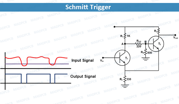
Schmitt Trigger
Schmitt trigger devices are simple circuits that accept an oscillating signal (e.g. a sawtooth or triangle wave) and output a square wave. They typically used in signal conditioning applications to remove noise from signals used in digital circuits, particularly mechanical contact bounce in switches. They are also used in closed loop negative feedback configurations to implement relaxation oscillators, used in function generators and switching power supplies.
The Schmitt trigger was invented by American scientist Otto H. Schmitt in 1934 while he was a graduate student, later described in his doctoral dissertation (1937) as a thermionic trigger. It was a direct result of Schmitt’s study of the neural impulse propagation in squid nerves.
Fundamental Circuit in ICs and PCBs
Schmitt triggers are fundamental circuits in integrated circuits (ICs) and simpler printed circuit boards (PCBs), and they can play an important role in cleaning up signals for use in other digital circuits. There are many different Schmitt trigger components and ICs, but they all reply on two important properties for rectification and stabilization of noisy input signals: saturation and hysteresis. Although these circuits are similar to amplifier circuits and even use the same symbol in a schematic, they operate quite differently.
When design a Schmitt trigger circuit for cleaning up noisy signals and producing digital pulses, the classic circuit diagram for Schmitt triggers is surprisingly resilient until get to very high frequencies. When need to evaluate the circuit, it’s recommended to run some simple SPICE simulations to test circuit behavior and verify that components will function as desired.
Schmitt Trigger vs. Comparator Circuits
Schmitt triggers are often compared to comparator circuits, as their behavior is quite similar. All Schmitt triggers are comparators, but not all compactors are Schmitt triggers. Both types of circuit use hysteresis to set a threshold for switching between two saturated states. For a comparator, the output is saturated at the supply rail voltages, and the output will cycle between the positive and negative saturation voltages (e.g. rail-to-rail). The reference voltage to induce switching can be set by placing pull-up and pull-down resistors around the inverting unput (or the non-inverting input for an inverting comparator). There is always a small hysteresis window in comparator circuits so that they can withstand ~10mV of fluctuations in the input. The circuit below shows a comparator built from an op-amp where the positive feedback loop causes saturation at the supply rail voltages.
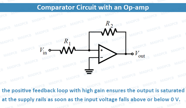
Comparator Circuit with an Op-amp 1
For Schmitt triggers, hysteresis is intentionally added to set the switching threshold to some desired value. For a transistor-based comparator, hysteresis can be applied to the output voltage with another positive feedback loop using a voltage divider. The values of the resistors in the voltage divider determine the size of the hysteresis window and the duty cycle of the output waveform. A general circuit for an inverting Schmitt trigger is shown below, which includes the hysteresis window on the output signal.
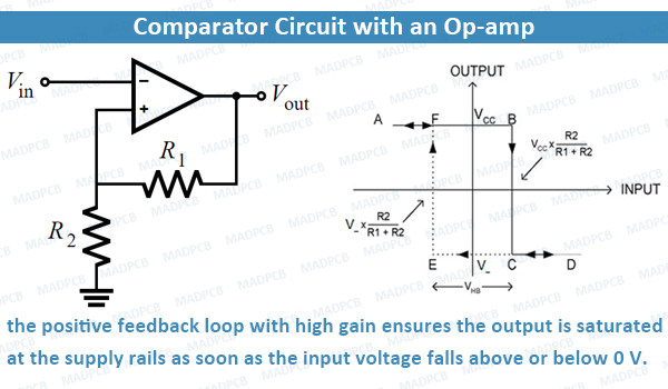
Comparator Circuit with an Op-amp 2
Using the same technique, you can create a Schmitt trigger with an op-amp, although op-amp manufacturers advise against this. The reason for this advice is that an op-amp is generally not designed to run at high gain deep into saturation. Instead, these components are designed to run in the linear range, and they cannot withstand the thermal demands of switching between saturation states for extended periods.
Input Ripple and Noise Rejection
Because the input is a differential input, a Schmitt trigger has a high common-mode rejection ratio (CMRR). Despite the high CMRR provided by the differential input, natural variations in the input signal could still cause unintended switching between the two output states. This should illustrate the reason that hysteresis can be added to a comparator. By widening the hysteresis window, the rising edge and falling edge transitions become more different, and the circuit can withstand a larger voltage fluctuation without unintended switching.
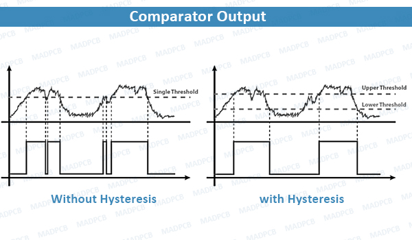
Comparator Output Without Hysteresis and with Hysteresis
Simulating Schmitt Triggers
A Schmitt trigger circuit can be simulated using transient analysis and DC analysis of the transistor stages involved. When built from transistors, these circuits need to operate at saturation, so a load line will need to be simulated with a DC sweep. Transient analysis allows you to measure the duty cycle of the output square wave, which can then be compared with your earlier analysis from a feedback loop.
If you’re designing high-frequency Schmitt triggers, such as circuits that will operate at high GHz frequencies, you’ll need to use the right model for your SPICE subcircuits. GaAs or GaN-SiC material models are normally used for these high-frequency analog circuits. These types of circuits are still an active area of research, but these circuits can provide a high GHz clock or PWM signal without using a PLL.
Whether you’re designing custom Schmitt triggers from transistors or you’re using an op-amp, you need good PCB design technique, or ask the help of our professional designers. At MADPCB, we provide one-stop PCB services, including PCB design, PCB manufacturing, PCB assembly, components sourcing, IC programming and functional testing. Forwarding your files and requirements to us, a quick quote can be offered, and suggestions.