What’s A Thick Film Resistor?
Thick Film Resistor is made by screen printing and firing conductive and resistive paste onto hard substrates, usually alumina (Al2O3). In thick film technology, alumina of reduced purity is used (95%) compared to thin-film (99%). Firing temperature is usually around 850°C. The resistor material is usually an oxide of ruthenium, iridium and rhenium, NOT carbon. Sometimes the resistor material is referred to as cermet (portmanteau of ceramic/metallic). The black color of the resistor body has nothing to do with a carbon element, resistor color has been reported as dark green in some instances. The resistive element is protected with a film that is colored black to provide contrast white text printed on it.
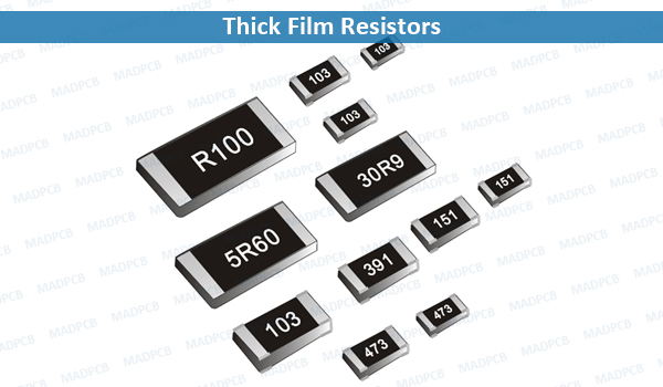
Thick Film Resistors
Thick film resistor is an additive process, as opposed to most thin film processes which are substractive (chemical etching). In some thick film parts, before resistors are deposited, a conductor pattern is printed and fired first. The conductor and resistor materials are deposited using a screen-printing process using a squeeze. Thick film resistors are almost less expensive than thin film.
Sheet resistance of thick-film resistors can be much higher than thin films, from 20 ohms per square up to 500K ohms per square. On a custom job, it is possible to use multiple pastes with widely-varying sheet resistivity, so that almost any resistance value can be accommodated, each in nearly the same area. Thick film resistor values can be laser trimming. Typical processes add an overcoat of glass, fired at 600°C, to protect the resistor. Temperature effects an electrical and mechanical stresses can all impact the performance of a resistor over time. They may affect the resistor value or cause complete failure.
Resistor Laser Trimming
After processing, thin and thick film resistors will always have some statistic variation from their intended value. In the case of separate chip resistors, parts can be measured, then binned into 10%, 5% or even 1% tolerances (standard RETMA values). In larger format thick film or thin film networks where the resistors are just one small detail in complex artwork, often the final part will not work if the resistor value deviated too much, and out-of-spec resistors means scrapped parts. The alternative is to trim the resistors into the correct value. In laser trimming, a YAG laser is used to ablate the resistor material from the substrate, raising its resistive value with any of three ways, including plunge-cut, edge-cut and L-cut.
SMD resistor is a deliberate type of device that embraces surface mount technology to offer significant benefits concerning automated manufacture and space-saving of PCBs, and improves the PCB assembly efficiency. That’s why, in most PCB manufacturing, you can see more copper pads with different surface finishes in quantities than PTHs.
Thick film resistors are used on literally every type of electrical device; if it has a battery or an AC plug, it will probably have a thick film resistor. For example, the average PC currently contains over 1200 chip resistors, most of which are thick film chip resistors. Unless there are stability, accuracy, or noise requirements, thick film resistors will always be the preferred resistive solution in any PCB design.