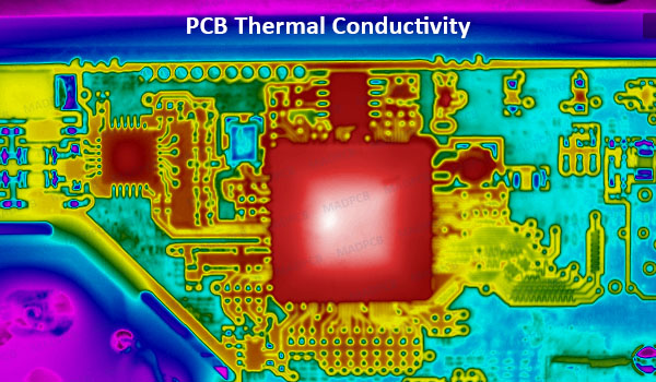
What Is Thermal Conductivity?
Thermal Conductivity (Κ, λ, or κ.) is an important physical quantity in PCB measures the rate at which heat flows away from a heat source and towards cooler regions of the PCB assembly (PCBA). The unit is W/m·K.
There are many substrate materials in PCB manufacturing:
| PCB Substrate Material | Thermal Conductivity (W/·mK) |
|
FR-4 |
0.8-11 |
| Alumina (Al2O3) |
28-35 |
|
Aluminum Nitride (AlN) |
140-180 |
| Beryllium Oxide (BeO) |
170-280 |
A PCB assembly consists of conductive material, insulators, and mounted components. Every material used in it has a different thermal conductance. The effective thermal conductivity of a PCB is not only limited to PCB substrate material. The varying thermal conductance is taken into consideration.
How to Improve PCB Thermal Management?
Various studies have been conducted to analyze thermal conductivity for a PCB. Depending on the study, different types of models and assumptions are used. As far as designers are concerned, the effective thermal conductivity for a PCB is dependent on a few factors. Here are some instructions on how to improve your PCB thermal conductivity or management as following:
- Thick Copper PCB: Thick copper circuit boards (eg 70μm, 105μm, max 350μm) improve the heat dissipation and thus allow heat distribution over large surfaces. The heat distribution occurs in the copper layer on the PCB surface and inner layers. Thick copper circuit boards are primarily used for high power (high current) applications and for cooling components with high thermal conductivity.
- Metal Core -IMS: Metal core, also called IMS (insulated metal substrate) PCBs are used to dissipate heat quickly and effectively from components. Due to its significant higher heat conductivity compared to FR4, IMS is widely used in LED applications, especially high power LEDs. In most applications, IMS circuit boards, along with a thermal interface material, like thermally conductive paste, are attached to a heat sink by screws. (like Aluminum board, is 1W/m·K)
- Trace Geometries: If you have copper traces that run along one end to the other, you can expect a high effective thermal conductivity value on the PCB. However, the value may decrease if the traces are discontinued, which is often the case in an actual PCB.
- Thermal via array: Thin, double-sided or multilayer printed circuit boards (PCBs) with array of thermal vias intentionally placed to dissipate heat off a component. These thermal vias are in two types, including simple vias, and filled & capped vias. It’s kind of like providing more opportunity for the steam to escape from your porridge instead of trapping it in a container. So, naturally, this means that the more thermal vias there are in an area, the more they will increase effective thermal conductivity of a board.
- Internal Layers: The presence of internal copper layers can also change the rate and direction of heat dissipation. The thermal conductivity for copper is 355W/mK, while FR-4 is 0.25W/m·K. With multiple inner-layers of copper, the effective thermal conductivity of the PCB would decrease. Of course, the presence of thermal vias could help to move the heat to the inner layers more efficiently.
- Ground and power planes: If a multilayer PCB, like a HDI board, the power and ground planes will both have high thermal conductance and dissipate heat throughout a board. However, they will not help reduce temperature to the same extent as ceramic boards as the temperature gradient between the board’s surface and the external environment tends to be lower than with ceramics. Including extra power and ground planes can provide some extra thermal dissipation, increasing the equivalent thermal conductivity of your PCB.
- Component size: As components become smaller, so does the ability to dissipate heat naturally. For example, as MOSFET with a SOT-23 package will have less area for its heat pad than one in TO-220. Therefore, the size of components mounted on a PCB will influence its ability to propagate heat.

