What Is HDMI?
High-Definition Multimedia Interface (HDMI) is a proprietary audio/video interface for transmitting uncompressed video data and compressed or uncompressed digital audio data from an HDMI-compliant source device, such as display controller, to a compatible computer monitor, video projector, digital TV, or digital audio device. HDMI is a digital replacement for analog video standards.
Backgrounds
HDMI implements the EI/CEA-861 standard, which define video formats and waveforms, transport of compressed and uncompressed LPCM audio, auxiliary data, and implementations of VESA EDIO. CEA-861 signals carried are electrically compatible with the HDMI adapter is used. The CEC (Consumer Electronics Control) capability allows devices to control each other when necessary and allows the user to operate multiple devices with one handheld remote control device.
Several versions have been developed and deployed since the initial release of the technology, but all use the same cable and connector. Other than improved audio and video capacity, performance, resolution and color spaces, newer versions have optional advanced features such as 3D, Ethernet data connection, and CEC extensions.
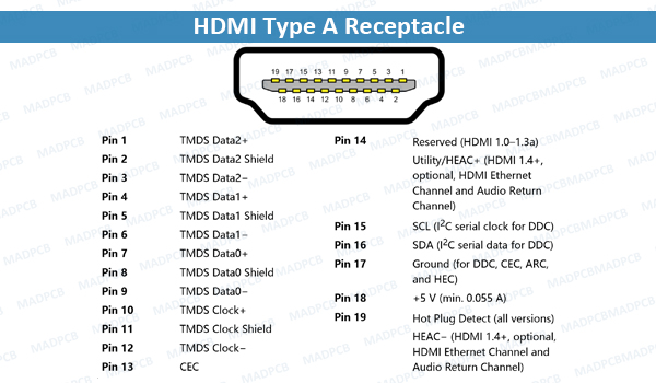
HDMI Type A Receptacle
Production of consumer HDMI products started in late 2003. In Europe, either DVI-HDCP or HDMI is included the HD ready in-store labeling specification for TV set for HDTV, formulated by EICTA with SES Astra in 2005. HDMI began to appear on consumer HDTVs in 2004 and camcorders and digitals still cameras in 2006. As of January 6, 2015 (12 years after release of the first specification), over 4 billion HDMI devices have been sold.
HDMI Connectors
There are female and male connectors with straight or right angles. And there are many kinds of connector adapters. In general, there are 5 types of connector.
- HDMI Type A Connector: This connector was launched with the original standard and has been the mainstay of the HDMI standard since then. The type A connector is the one that is the most familiar to users of AV equipment and it is found on a huge number of items from televisions, DVD plays, satellite boxes, recorders, games consoles and many more items. Where space is not an issue, the type A connector is ideal as it is the most robust. The plug or male connector has outside dimensions of 13.9 mm × 4.45 mm, and the receptacle or female connector has inside dimensions of 14 mm × 4.55 mm. There are 19 pins and the bandwidth is able to carry all SDTV, EDTV, HDTV, UHD, and 4K modes. This connector type is electrically compatible with single-link DVI-D. The male version of the Type A connector is widely available on ready-made leads as well as connectors for self assembly. Many of the female versions are also available for incorporation into AV equipment. There is a good selection, so the one with the required dimensions, format and specification can be chosen.
- HDMI Type B Connector: The Type B connector was also launched with the original standard in 2002 and it is aimed at carrying dual link DVD-I video. The connector has never been used in products because with the introduction of 1.3, the speed of a single link exceeded that of the old dual link. As the connector is larger than the single link standard style, there has been no reason for its use. However, it is still retained within the specifications. This type of connector measures 21.2 mm × 4.45 mm and has 29 pins, carrying six differential pairs instead of three.
- HDMI Type C Connector – Mini-HDMI Connector: This is the mini-HDMI connector and is smaller than the Type A connector, measuring 10.42 mm × 2.42 mm but still retaining the 19-pin configuration. The mini-HDMI retains all the functionality of the larger Type A, but the connector is much smaller. The HDMI mini connector was introduced in Version 1.3 as the standard became more widely accepted and the need for a smaller connector was recognized. There are differences in the mini-HDMI connector connection configuration: all positive signals of the differential pairs are swapped with their corresponding shield, the DDC/CEC Ground is assigned to pin 13 instead of pin 17, the CEC is assigned to pin 14 instead of pin 13, and the reserved pin is 17 instead of pin 14. The Type C connector can be connected to a type A connector but it requires the use of a type A-to-type C cable or an adapter. The mini-HDMI connectors are very common on many pieces of portable equipment. Some examples include: DSLR cameras, camcorders, larger tablets, sat nav systems and the like.
- HDMI Type D Connector – micro-HDMI Connector: The size of the Type D connector is very similar to the micro-USB connector and as a result the Type D is often known as a micro-HDMI connector. The measurements are just 6.4 mm × 2.8 mm and within this outline the micro-HDMI retains the 19 pins of the other connectors, although the pin assignments are different. The micro-HDMI connector was introduced with Version 1.4. It was developed specifically for audio-video connectivity in small and portable devices like mobile phones.
- HDMI Type E Connector: The Type E connector is aimed at automotive applications. This connector was introduced with Version 1.4. In order to prevent it vibrating loose it incorporates a locking tab and also a shell to help prevent dirt and moisture from entering. Additionally, a relay connector is available for connecting standard consumer cables to the automotive ones and enabling an interface to consumer AV items which is happening increasingly.
13 Layout Rules of HDMI PCB
Normally HDMI traces on printed circuit boards (PCBs) are very short, directly from the connector to the receiver/transmitter. Many times, we get the question of how long can I make HDMI traces. The specification does not define maximum length, only expected impedance. As long as you follow the following layout rules you should be able to run HDMI traces over 20-30cm easily. Longer if you are careful.
- Each HDMI channel is comprised of 4 TMDS pairs.
- Each HDMI channel set shall be routed primarily on the top or bottom layer as a group or alternately routed as a group on internal layers.
- Each TMDS signal shall have single ended impedance of 50 Ω ± 10%.
- Each TMDS pair shall have differential impedance of 100 Ω ± 5%.
- Signals within a TMDS pair shall have matching lengths of ± 3mm.
- Signals within a TMDS pair shall not have any 90° corners. Corners shall be chamfered.
- TMDS signal chamfer length to trace width ratio shall be 3 to 5.
- TMDS signal distance between bends should be 8 to 10 times the trace width
- TMDS pairs in each HDMI channel shall have matching lengths of ± 3mm.
- TMDS pairs shall be separated from adjacent TMDS pairs by a minimum of 1.2 mm.
- TMDS pairs shall be separated from adjacent non-pair signals by a minimum of 7.8 mm.
- HDMI channel sets shall be separated from other channel sets by a minimum of 7.8 mm.
- HDMI channel sets shall be referenced to an adjacent solid ground plane.
If a HDMI channel set must transition to another reference ground plane then ground plane to ground plane vias must be added adjacent to the channel transition vias.
The following is a general set of HDMI PCB fabrication notes placed on the PCB fabrication drawing. They allow the PCB fabricator to tweak the Gerber to match their process and materials.
- Characteristic impedance of all signal layers to be 50 Ω ± 10%
- Differential impedance of 0.127mm (5mil) traces with 0.192mm (7.559mil) gap shall be 100Ω ± 10%. PCB supplier may adjust trace widths, trace spacings and dielectric thickness as required.
How to Handle Reference Plane Transitions?
HDMI components are designed so routing is a straight shot from the device pin to the connector pin. However, sometimes you need to change layers the HDMI routing is done on, often changing the reference ground plane in the process. The transition vias should be symmetrically placed in the path and ground to ground vias to handle the signal integrity of reference plane jumping as illustrated below.
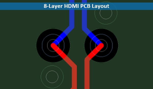
8-Layer HDMI PCB Layout
This particular example is from an eight-layer HDMI board in the above figure, the red trace is on the top layer, the blue trace is on the bottom layer and the dark green layers are the solid ground planes adjacent to the top and bottom layers. Note that the vias are place symmetrically in the path and separated by 1.14mm. Also note the 2 ground vias adjacent to the 2 trace vias.
In this example if the differential pair jumped from layer 1 to layer 3, no ground-to-ground vias would need to be added since you are not jumping reference ground planes.
It is best to keep the number of differential pair vias to a minimum since each via introduces impedance changes.
It is also a good idea to stitch ground to ground vias along the trace path every 2 cm or so. This aids in general signal integrity control.