What’s Thermal Stability in PCB?
Thermal Stability is defined as the ability of a PCB to resist breaking down under heat stress, and maintain stable characteristics in spite of increased temperature. The maximum use temperature is the suggested maximum temperature to which the PCB can be heated before the PCB begins to break down or degrade at an appreciable rate. Thermal stability is mainly affected by thermal conductivity, thermal resistance, CTE and Tg of PCB materials.
The following are these thermal properties connected to PCB thermal stability.
Dimensional Tolerances of Thermal Stability
Rigid board outline must fit within its enclosure, flex circuit must fit within its connecting length. The product communicates with the outside world through interfaces (like USB, HDMI port) mounted on the board that poke outside of the housing.
Poor thermal stability of your printed circuit board (PCB) will cause dimension beyond tolerance. In PCB fabrication process, especially for flexibles, if thermal expansion of the flex materials is large, the coverlay openings on pads will be dis-aligned, drilling deviation will be much and may break the circuits in inner layers.
PCB materials, like CCL and FCCL, have some important thermal properties which take into considerations in PCB design, manufacturing and assembly. Not all circuit boards are developed and worked in harsh environments, but those are need to remain reliable throughout their life span. High temperatures, repeated thermal cycling, moisture uptake, and low glass transition temperature can cause problems during board manufacturing and operation. If you pay attention to the right thermal properties of your substrates, you can ensure thermal stability.
Thermal Conductivity and Thermal Resistance
Thermal conductivity probably receives the most attention among all the possible properties of PCB base materials after loss tangent. This is sometimes used interchangeably with thermal resistance. Although the two are related, they are not the same.
Thermal conductivity is the thermodynamic analogue of electrical conductivity. It defines the rate at which heat is transported along a temperature gradient per unit area. The thermal resistance of your PCB substrate depends on a related quantity, which is the effective thermal conductivity. The effective thermal conductivity is proportional to the individual thermal conductivity values of each material (copper foil, core/PP, resin, etc.) on the board. Datasheets quote a thermal conductivity value for a bare laminate material.
If you need to quickly dissipate heat from the components, then you need a larger thermal conductivity. Some alternatives to FR-4 can provide much higher thermal conductivity. Ceramics in ceramic PCB are one notable example, as they have very high thermal conductivity values compared to glass weave laminates. Metal-core substrates are also an excellent choice; these materials are typically used with high power LED boards.
Coefficient of Thermal Expansion (CTE)
Every material expands or contracts as temperature changes. CTE values define how much the volume of a material increases when its temperature increases. Unless you’re working with water below 4°C, CTE values are always positive. For copper, the coefficient of thermal expansion is ~17 ppm/°C, while this value varies for different substrate materials, a typical value for FR4 is 11 along the board surface and 15 perpendicular to the board surface. Other materials, such as ceramics, can have a broad range of CTE values. As an example, aluminum nitride is very useful for its high thermal conductivity, but the CTE vales is quite low (from 4.3 to 5.8 ppm/°C).
CTE is important both at high temperature and when the board temperature is repeatedly cycled between high and low values. During cycling, the board will expand and contract, which places stress on copper elements, and this stress is larger when the mismatch between the substrate and copper CTE values is larger. The CTE values for your conductors and substrate materials should match as closely as possible.
For low aspect ratio vias and reasonably thick trace, a CTE mismatch is not such a problem. However, high aspect ratio vais will experience stress concentration in the middle of the barrel and at the neck, requiring a thicker plating or filling to ensure a conductive path if a via cracks. In HDI boards, repeated stress accumulation due to cycling is known to lead to cracking at via necks.
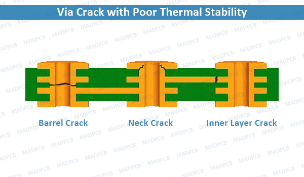
Via Crack with Poor Thermal Stability
Glass Transition Temperature (Tg)
CTE value of any material generally increases with temperatures. Glass transitions tend to occur in amorphous materials; once the temperature of a material exceeds its glass transition temperature, the slope of the material’s CTE vs. temperature curve experiences a steep increase. This means the material experiences greater expansion with temperature changes when the temperature exceeds Tg.
In glass-weave substrate materials, one way to increase the range of useful temperature values and avoid a glass transition is to use a substrate with a high-Tg resin. Standard FR4 has a Tg value of ~130°C, but a substrate with a high-Tg resin can bring the Tg value up to ~170°C or even higher. If your substrate and conductor CTE values were closely matched at low temperature, and your circuit board will operate at high temperatures, then you should opt for a substrate with a higher Tg value.
Most boards will probably not run above the standard ~130°C Tg value. What is more important is the thermal stability of CTE as a function of temperature, as an excessive CTE value at high temperature creates more stress on thin conductors. If your board will be frequently cycled to high temperatures, I would opt for a more stable CTE value that is close to the conductor value.